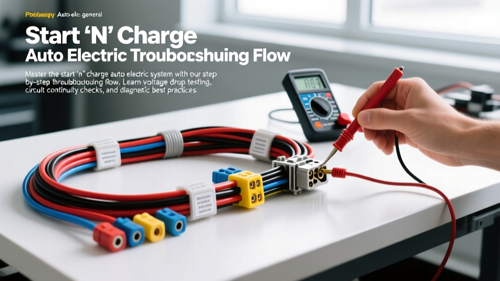
Mastering the Start 'N' Charge Auto Electric Diagnostic Flow
When diagnosing a no-crank, slow-crank, or battery warning light issue, understanding the complete start 'n' charge auto electric architecture is critical. Modern vehicles rely on complex Pulse Width Modulation (PWM) charging strategies and PCM-controlled starter relays, making simple continuity testing obsolete. To accurately diagnose these circuits, technicians must rely on dynamic voltage drop testing under load. This guide provides a comprehensive, step-by-step troubleshooting flow for both the cranking and charging circuits, complete with AWG specifications, pin configurations, and SAE-standard voltage drop limits.
Phase 1: The Foundation - Battery State of Charge (SOC)
Before testing any starter or alternator circuit, the battery must be verified as fully charged and capable of holding a load. A surface charge will skew all subsequent voltage drop readings. Apply a carbon pile load test or use an electronic conductance tester to verify Cold Cranking Amps (CCA). For open circuit voltage (OCV) verification, ensure the battery has rested for at least 4 hours after charging.
| State of Charge | OCV (Flooded Lead-Acid) | OCV (AGM) |
|---|---|---|
| 100% | 12.66V | 12.80V - 13.00V |
| 75% | 12.45V | 12.60V |
| 50% | 12.24V | 12.30V |
| 25% | 12.06V | 12.00V |
| 0% | 11.89V | 11.80V |
Phase 2: The Cranking Circuit (Start) Decision Tree
The starter circuit is divided into two distinct sub-circuits: the high-amperage power circuit and the low-amperage control circuit. Use this step-by-step flow to isolate failures.
Step 1: Symptom Verification & Control Circuit Check
Symptom: Turn key to START, no click, no crank.
- Verify PCM/Immobilizer Status: Check for security light on the dash. Use a scan tool to verify the PCM sees the 'PRNDL' in Park/Neutral.
- Locate Starter Relay: Listen for the relay click in the under-hood fuse box. If no click, check the relay coil ground (usually PCM controlled) and ignition switch feed.
- Test Solenoid 'S' Terminal: Disconnect the trigger wire at the starter solenoid. Attach a test light or DVOM between the harness connector and battery ground. During crank attempt, you should see 11.5V+ (or test light illumination).
- GM Vehicles: Typically Purple or Purple/White 14 AWG wire.
- Ford Vehicles: Typically Red/Light Blue 14 AWG wire.
- Toyota/Honda: Typically Black/White or Black/Yellow 16 AWG wire.
- Conclusion: If voltage is present at the 'S' terminal but the starter does not engage, the solenoid or starter motor is faulty. If no voltage, trace back through the starter relay, neutral safety switch, and ignition switch.
Step 2: High-Amperage Power Circuit Voltage Drop
Symptom: Slow crank, clicking, or starter draws excessive amperage.
- Setup DVOM: Set to DC Volts (mV scale if possible). Place positive lead on Battery B+ post (NOT the clamp) and negative lead on the Starter BAT terminal stud.
- Crank Engine: Disable ignition/fuel to allow continuous cranking. Read the voltage drop.
- Specification: Maximum 0.20V drop for the entire positive cable assembly (typically 1/0 AWG or 2 AWG).
- Per Connection: Maximum 0.10V drop per mechanical connection (e.g., battery post to clamp, fuse block lug, starter nut).
- Torque Verification: If voltage drop exceeds limits, clean and retorque. Starter B+ nuts on 8mm studs should be torqued to 10-15 Nm; 10mm studs require 15-20 Nm. Battery terminal clamps require 5-8 Nm.
Step 3: Starter Ground Path Voltage Drop
- Setup DVOM: Positive lead on Battery Negative post, negative lead on the Starter motor housing (bare metal).
- Crank Engine: Maximum allowable drop is 0.10V. If higher, inspect the main battery ground cable (usually 2 AWG or 4 AWG) where it bolts to the engine block or chassis. Ensure no paint or corrosion is trapped under the ring terminal.
Phase 3: The Charging Circuit (Charge) Decision Tree
Modern alternators are rarely simple 'dumb' generators. They are controlled by the PCM via LIN bus or PWM signals. According to AutoShop101's Electrical Diagnostics Guide, testing the output requires verifying both the physical wiring and the control signals.
Step 1: Alternator B+ and Ground Voltage Drop
Symptom: Battery light on, measured battery voltage below 13.5V at idle with loads on.
- Positive Side Drop: DVOM positive on Alternator B+ output stud, negative on Battery B+ post. Run engine at 2000 RPM with headlights and blower motor on HIGH (to force maximum alternator output). Maximum allowable drop is 0.20V. The B+ cable is typically 4 AWG to 8 AWG, often routed through a high-amperage mega-fuse (125A-175A) in the under-hood fuse block.
- Ground Side Drop: DVOM positive on Battery Negative post, negative on Alternator rear housing. Maximum allowable drop is 0.10V. Alternators ground through their aluminum mounting brackets to the engine block. If the drop is high, install a dedicated 8 AWG ground strap from the alternator housing to the engine block.
Step 2: Regulator and Sense Circuit Verification
If the physical power and ground paths are verified, the issue lies in the control/sense circuitry. The alternator needs to know what voltage is actually at the battery to adjust its field current.
GM CS130D / CS144 4-Pin Connector Deep Dive
General Motors utilized a 4-pin connector (P, L, I, S) that is a frequent source of misdiagnosis. The connector uses 14 AWG to 18 AWG wires.
- Pin P (PCM): PWM signal from the Powertrain Control Module to command specific voltage targets (e.g., 13.9V for fuel economy, 14.8V for charging).
- Pin L (Lamp): Feeds the instrument cluster charge indicator lamp. Usually pulls to ground internally if a fault is detected.
- Pin I (Ignition): 12V+ from the ignition run circuit to wake up the internal regulator.
- Pin S (Sense): Critical. This wire (typically 14 AWG Red or Orange) must be routed directly to the main battery positive junction or fuse block. It must be fused (usually 10A-15A) within 7 inches of the power source. If the Sense wire loses voltage, the alternator will default to a limp-home mode of ~13.8V or shut down entirely to prevent overcharging.
Ford 3G 3-Pin Regulator Connector
Ford's 3G alternator uses a 3-pin connector (A, S, I).
- Pin A (Battery/Sense): Connected directly to the B+ output stud via a 10A inline fuse. Provides local voltage sense.
- Pin S (Stator): Connected internally to the stator windings to prove rotation before the regulator turns on the field.
- Pin I (Ignition): Ignition switch 12V+ feed to activate the regulator.
Phase 4: SAE Voltage Drop Specification Reference
Adhering to Society of Automotive Engineers (SAE) standards ensures that your diagnostic conclusions are based on empirical data, not guesswork. As noted in AA1Car's comprehensive guide on voltage drop testing, high resistance creates heat, which increases resistance further, leading to cascading electrical failures.
| Circuit Component | Maximum Voltage Drop | Typical AWG Size |
|---|---|---|
| Single Mechanical Connection (Post/Terminal) | 0.10V (100mV) | N/A |
| Entire Starter Positive Cable Assembly | 0.20V (200mV) | 1/0 AWG - 4 AWG |
| Entire Starter Ground Path | 0.10V (100mV) | 2 AWG - 4 AWG |
| Alternator B+ Output Cable | 0.20V (200mV) | 4 AWG - 8 AWG |
| Alternator Ground Path (Housing to Block) | 0.10V (100mV) | N/A (Case Ground) |
| Standard 12V Lighting/Accessory Circuit | 0.50V Total | 14 AWG - 18 AWG |
Expert Troubleshooting Insights & Common Failure Modes
1. The 'Clean but Loose' Fallacy: A battery terminal can look perfectly clean and shiny, but if the clamp is stretched and lacks proper clamping force, it will arc under the 200A+ load of the starter. This causes voltage spikes that can fry sensitive PCM drivers. Always use a terminal spreader tool to check clamp tension.
2. Alternator Decoupler Pulleys: Many modern vehicles use Overrunning Alternator Pulleys (OAP) or Overrunning Alternator Decouplers (OAD). If the internal one-way clutch seizes, the alternator will overcharge at idle and cause severe belt slap. Always check the pulley with the correct OAP spline tool during a charging system diagnosis.
3. Parasitic Draws Masking as Charging Faults: If a customer complains of a dead battery every morning, but the start 'n' charge auto electric tests all pass perfectly, perform a parasitic draw test. Modern vehicles should drop below 50mA (0.050A) within 20 minutes of shutdown. Common culprits include aftermarket amplifiers, stuck HVAC blend door actuators, and faulty telematics modules.
Summary
Diagnosing the start and charge systems requires a methodical approach. By verifying the battery state of charge, performing dynamic voltage drop tests on high-amperage cables, and verifying the specific pinouts of PCM-controlled alternator regulators, you can accurately pinpoint faults on the first attempt. Always reference manufacturer wiring diagrams for exact wire colors and pin configurations, and rely on your DVOM rather than test lights for modern low-current control circuits.