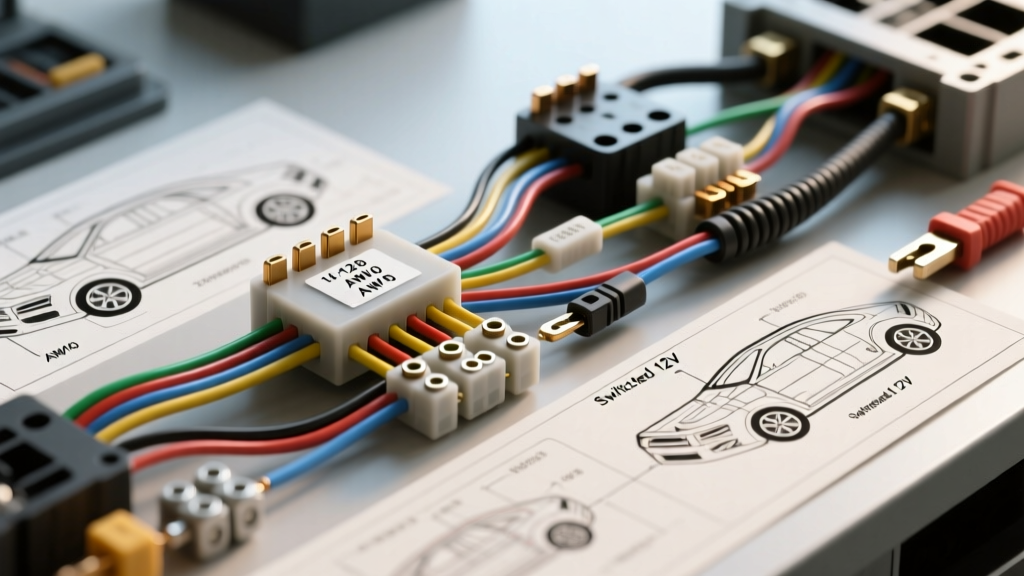
Mastering the Valentin Auto Electric Hardwire Integration
When automotive enthusiasts and 12V integration specialists reference a Valentin auto electric configuration, they are generally addressing the seamless, hardwired installation of premium radar and laser detection systems—most notably the Valentine V1 Gen2—into complex modern vehicle electrical architectures. Unlike simple cigarette lighter plug-ins, a true Valentin auto electric hardwire setup eliminates cabin clutter, ensures reliable switched power, and protects the vehicle's sensitive CAN-bus networks from parasitic draws and electromagnetic interference (EMI).
This comprehensive guide details the exact electrical specifications, wire routing protocols, and fuse-tapping methodologies required to execute a factory-grade radar detector installation without triggering dashboard fault codes or compromising safety systems.
Electrical Specifications and Material Requirements
Modern radar detectors are highly sensitive electronic devices. Supplying them with clean, stable 12V DC power is critical to prevent false alerts, reboots, or alternator whine induced by ground loops. Below are the strict electrical parameters for a standard high-performance radar hardwire kit.
| Parameter | Specification | Technical Notes |
|---|---|---|
| Operating Voltage | 11.5V - 14.8V DC | Must handle peak alternator output without triggering over-voltage protection. |
| Max Current Draw | 350mA (Peak) | Occurs during initial GPS lock and multi-radar signal processing. |
| Wire Gauge | 18 AWG (SAE J1128 GPT) | Primary wire rated for 125°C. Do not use thinner 20 AWG or 22 AWG speaker wire. |
| Inline Protection | 2A or 3A ATO/Mini Fuse | Protects the hardwire tap and device; prevents thermal events in the event of a short. |
| Ground Termination | M6 / M8 Ring Terminal | Must connect to bare, unpainted chassis metal with 8-10 Nm of torque. |
The OBD2 Tap vs. Add-A-Fuse Debate
A common shortcut in the Valentin auto electric community is using an OBD2 port tap. While this provides easy access to constant 12V (Pin 16) and chassis ground (Pin 4), it is strongly discouraged for modern vehicles (2015+). Tapping the OBD2 port risks interfering with the CAN-bus network, specifically if the tap bridges or introduces capacitance to Pin 6 (CAN-High) and Pin 14 (CAN-Low). Furthermore, OBD2 taps often draw from constant battery power, leading to parasitic drains that can kill a vehicle's AGM battery over a weekend.
Instead, utilizing an Add-A-Fuse (fuse tap) at the interior fuse panel is the industry standard. This method allows you to isolate a switched 12V circuit, ensuring the radar detector powers on and off precisely with the vehicle's ignition cycle.
Step-by-Step Valentin Auto Electric Installation Guide
Step 1: Identifying a Switched 12V Accessory Circuit
Using a digital multimeter (DMM) set to DC Voltage, probe the test points on the top of the mini-fuses in the interior fuse box.
Testing Protocol:
1. Set the DMM black probe to a known chassis ground.
2. With the ignition OFF and the key removed, probe the fuse test points. A reading of 0V indicates a switched circuit or an inactive circuit.
3. Turn the ignition to the ON/RUN position (without starting the engine). Probe the same fuse. A reading of 12.0V - 12.6V confirms a switched accessory circuit.
Target Circuits: Heated seat modules, 12V auxiliary power outlets, or wiper delay circuits. Never tap airbag (SRS), ABS, BCM, or fuel injection fuses.
Step 2: Proper Add-A-Fuse Orientation
A critical failure mode in amateur Valentin auto electric installs is inserting the Add-A-Fuse backwards. The fuse tap has a line side (power from the bus) and a load side (power to the accessory). If inserted incorrectly, the original vehicle circuit and the new radar circuit will both draw power through a single fuse, potentially overloading it and causing a fire hazard. Use your DMM to verify that the original vehicle fuse is protected by its designated amperage, and the new radar tap is protected by the 2A/3A fuse you installed in the secondary slot.
Step 3: A-Pillar Routing and Airbag Safety
Route the 18 AWG hardwire cable up the A-pillar to the headliner. Safety Warning: If your vehicle is equipped with side-curtain airbags, the wiring must be routed behind the airbag deployment path, secured tightly to the factory wiring harness using nylon zip-ties. Never let aftermarket wiring cross over or sit on top of an airbag module, as it can become a lethal projectile during deployment or impede the airbag's inflation trajectory.
Step 4: Establishing a Clean Chassis Ground
Locate a factory grounding bolt near the fuse panel or kick panel. Remove the bolt, use a fiberglass scratch brush to remove any paint, primer, or corrosion from the mating surface, and attach your M6 ring terminal. Reinstall the bolt and torque it to 10 Nm. Apply a dab of dielectric grease over the terminal to prevent future oxidation, which can introduce resistance and cause the radar detector to reboot during high-draw events like engine cranking.
Step 5: Voltage Drop Testing the Ground Circuit
Before finalizing the headliner and A-pillar trim, perform a voltage drop test on your new ground connection. Set your DMM to DC millivolts (mV). Place the red probe on the negative terminal of the vehicle battery and the black probe on the ring terminal of your radar hardwire kit. Turn the radar detector on (or simulate a load). A reading above 100mV (0.1V) indicates excessive resistance in the ground path, likely due to paint or corrosion. Scrape the contact point again and re-torque. A solid ground is paramount; as noted in SAE J1113 EMC guidelines, poor grounding is the primary culprit for high-frequency EMI radiation that can trigger false laser alerts on sensitive receivers.
Understanding CAN-Bus Sleep Mode and Parasitic Draw
Modern vehicles utilize a multiplexed CAN-bus network that remains active for up to 20 minutes after the ignition is turned off. During this time, modules communicate, update odometers, and perform self-diagnostics. If your Valentin auto electric setup taps a circuit that keeps the Body Control Module (BCM) awake, the vehicle will never enter sleep mode. This results in a parasitic draw of 1.5A to 3.0A, which will completely deplete a standard 70Ah AGM battery in a matter of days. Always use an inline ammeter in series with the battery negative terminal to verify that the vehicle's total sleep-mode draw drops below 50mA after the CAN-bus timeout period.
Troubleshooting Common Electrical Faults
| Symptom | Probable Cause | Diagnostic Fix |
|---|---|---|
| Alternator Whine in Audio | Ground Loop | Ensure radar ground and audio headunit ground share the same chassis potential. Install a 12V DC ground loop isolator if necessary. |
| Detector Reboots on Cranking | Voltage Drop at Ground | Check ground terminal for corrosion. Voltage drop across the ground wire during cranking should not exceed 0.1V. |
| Parasitic Battery Drain | Tapped Constant 12V Fuse | Re-test fuse with DMM. Ensure the tapped circuit drops to 0V within 15 minutes of the vehicle entering sleep mode (CAN-bus shutdown). |
| CAN-bus U-Codes (e.g., U0100) | OBD2 Tap Interference | Remove OBD2 tap immediately. Relocate power source to a dedicated switched Add-A-Fuse circuit to restore network integrity. |
Authoritative References and Standards
- Valentine Research V1 Gen2 Official Documentation - Manufacturer specifications for power input tolerances and RJ11/USB-C hardwire adapters.
- SAE J1113: Electromagnetic Compatibility Standards - Guidelines for minimizing EMI and ensuring aftermarket electronics do not disrupt vehicle CAN-bus networks.
- Littelfuse Automotive Fuse Holder Specifications - Engineering data for Add-A-Fuse load distribution and thermal limits.
By adhering to these strict Valentin auto electric protocols, you ensure that your radar detection system operates flawlessly while maintaining the safety and electrical integrity of the host vehicle.