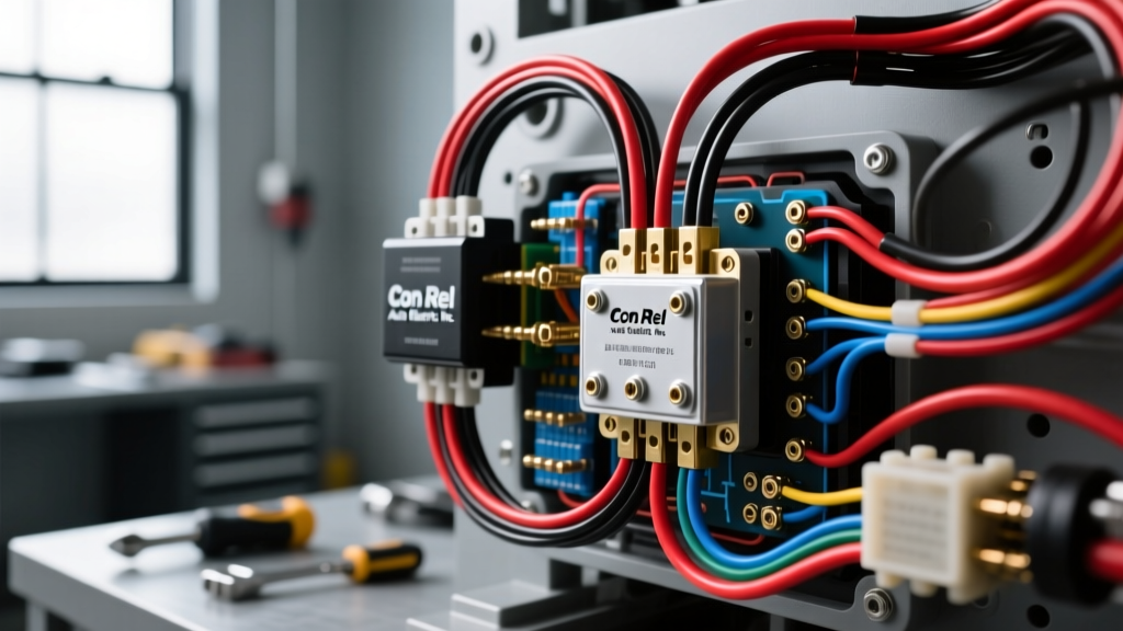
Introduction to Heavy-Duty Relay Integration
Modern automotive electrical architectures rely heavily on precise power distribution. When outfitting fleet vehicles, off-road platforms, or custom auxiliary systems with heavy-duty contactors and ISO mini relays sourced from specialized distributors like Con Rel Auto Electric Inc, technicians must adhere to strict electrical standards. While these components are built to withstand harsh under-hood environments, the vast majority of electrical failures do not stem from the relay itself. Instead, they originate from improper wiring, incorrect wire gauge selection, and a fundamental misunderstanding of coil suppression.
This guide outlines the most critical safety warnings and common wiring mistakes encountered when integrating heavy-duty automotive relays. By following these SAE-aligned protocols, you can prevent thermal runaway, ECU damage, and catastrophic harness fires.
Critical Safety Warnings Before You Begin
Before cutting, crimping, or testing any circuit connected to a vehicle's primary power distribution center, you must observe the following safety protocols:
- Negative Battery Isolation: Always disconnect the negative battery terminal first and secure it away from the battery post. Wait a minimum of 5 minutes before working near SRS (airbag) modules or infotainment CAN-bus gateways to allow backup capacitors to discharge.
- Arc Flash Prevention: Heavy-duty contactors (often used in winch or PTO applications) can arc violently if disconnected under load. Never unplug a heavy-duty relay socket while the circuit is energized.
- Insulated Tooling: Use VDE-certified insulated wrenches when working near the main B+ junction block or starter motor terminals to prevent accidental short-circuiting to the chassis ground.
The 5 Most Common Wiring Mistakes (and How to Fix Them)
Mistake 1: Misidentifying ISO Pin 87 vs. 87a
The standard ISO 7588 mini relay features five pins: 30 (Common Power), 87 (Normally Open Load), 87a (Normally Closed Load), 85 (Coil Ground), and 86 (Coil Power). A frequent error occurs when technicians assume the physical orientation of pins 87 and 87a is universal across all manufacturers. Many aftermarket sockets, including some universal harness kits, reverse the 87 and 87a cavities. Always verify the pinout using a multimeter in continuity mode before applying 12V power. Energize the coil (pins 85 and 86) and confirm that continuity shifts from 30-87a to 30-87.
Mistake 2: Undersizing the Load Circuit Wire Gauge
When wiring a 40A continuous-duty relay for auxiliary lighting or an electric fan, relying on standard 14 AWG wire is a severe fire hazard. According to SAE J1128 standards for low-tension primary cable, wire current capacity degrades significantly in high-temperature engine bay environments (up to 125°C). A 40A load requires a minimum of 10 AWG GXL or TXL cross-linked polyethylene wire. Using undersized wire increases resistance, leading to excessive voltage drop and thermal melting of the relay socket housing.
Mistake 3: Ignoring Coil Suppression (Flyback Diodes)
Relay coils are inductive loads. When the ECU or a manual switch cuts power to the coil (pins 85/86), the collapsing magnetic field generates a high-voltage reverse spike (inductive kickback) that can exceed 100V. If this relay is triggered by a solid-state ECU driver or a CAN-bus controller, this spike will instantly destroy the internal transistor. Always install a flyback diode (such as a 1N4004 or 1N4007) in parallel with the coil. The diode's cathode (stripe) must face the positive 12V trigger wire, allowing the reverse spike to recirculate harmlessly through the coil until it dissipates.
Mistake 4: Relying on Chassis Grounds for High-Current Coils
While grounding the relay coil (Pin 85) to a nearby chassis bolt seems convenient, modern unibody vehicles use extensive e-coating and sound-deadening materials that create high-resistance ground paths. A poor ground increases the coil's resistance, reducing the electromagnetic pull. This causes the relay contacts to "chatter" or partially engage, leading to arcing and pitting on the internal copper contacts. Always run a dedicated 18 AWG ground wire directly to a verified, clean chassis ground point or back to the ECU ground bus.
Mistake 5: Soldering Instead of Cold-Crimping
Solder wicks into the wire strands via capillary action, creating a rigid stress riser at the edge of the solder joint. In high-vibration automotive environments, this rigid section will fatigue and snap. Furthermore, solder has a lower melting point than copper; in a high-current fault condition, the solder will melt before the fuse blows, causing a short. Always use open-barrel crimp terminals with a ratcheting crimper calibrated to the specific AWG, followed by adhesive-lined marine-grade heat shrink to seal out moisture and prevent galvanic corrosion.
Con Rel Auto Electric Inc Relay Pinout & Specification Chart
The following reference table outlines the standard wiring specifications for heavy-duty 5-pin ISO relays commonly utilized in auxiliary power distribution modules.
| ISO Pin | Function | Recommended AWG (TXL/GXL) | Typical Wire Color Code | Max Continuous Current | Terminal Type |
|---|---|---|---|---|---|
| 30 | Common Power Input (B+) | 10 AWG (or 8 AWG for 50A+) | Red with Inline Maxi-Fuse | 40A - 70A | 6.3mm Spade / Ring |
| 87 | Normally Open (N.O.) Load Output | 10 AWG | Blue or Black | 40A | 6.3mm Spade |
| 87a | Normally Closed (N.C.) Load Output | 12 AWG | White | 20A | 6.3mm Spade |
| 86 | Coil Power Input (Trigger) | 18 AWG (16 AWG for long runs) | Yellow or Green | 150mA - 250mA | 2.8mm Metri-Pack |
| 85 | Coil Ground / ECU Driver | 18 AWG | Black | 150mA - 250mA | 2.8mm Metri-Pack |
Voltage Drop Testing & Thermal Safety Protocol
After installing any relay harness, you must perform a voltage drop test under load to verify the integrity of your crimps and wire sizing. Set your digital multimeter to the DC Millivolt (mV) scale.
- Connect the red probe to the positive battery post and the black probe to the load side of the relay (Pin 87 terminal). With the circuit energized, a reading above 500mV (0.5V) indicates excessive resistance in the power feed (undersized wire or poor crimp).
- Connect the red probe to the coil ground pin (Pin 85) and the black probe to the negative battery post. A reading above 100mV (0.1V) indicates a faulty chassis ground connection.
- Use an infrared thermometer to scan the relay socket housing and inline fuse holders after 15 minutes of continuous operation. Any component exceeding 85°C (185°F) requires immediate teardown and inspection for terminal fretting or insufficient wire gauge.
Diagnostic Decision Tree: Relay Clicks but Load Fails to Power
When troubleshooting a circuit where the relay audibly engages but the accessory (e.g., fuel pump, cooling fan) remains dead, follow this diagnostic path:
- Step 1: Check B+ at Pin 30.
- No Voltage: Trace back to the main fuse block. Check for blown primary fuses or corroded battery distribution lugs.
- 12V Present: Proceed to Step 2.
- Step 2: Jumper Pins 30 and 87 manually with a fused jumper wire.
- Accessory Powers On: The relay's internal contacts are likely pitted or carbon-scored, preventing high-current flow despite the coil engaging. Replace the relay.
- Accessory Remains Dead: The fault lies downstream of the relay socket. Proceed to Step 3.
- Step 3: Verify Ground at the Accessory.
- Poor Ground: Clean the accessory ground ring terminal, remove paint/corrosion from the mating surface, and torque to manufacturer specifications (typically 8-10 Nm for M6 bolts).
- Good Ground: Perform a voltage drop test on the wire between Pin 87 and the accessory to locate a broken strand or corroded intermediate connector.
Authoritative References & Further Reading
For deeper technical specifications regarding automotive relay integration and wiring standards, consult the following industry resources:
- SAE J1128: Low Tension Primary Cable Standard - Defines the thermal and physical requirements for automotive wire insulation, including GXL and TXL specifications.
- HELLA TechWorld: Automotive Relay Fundamentals - Comprehensive guide on ISO mini relay pinouts, contact materials, and coil suppression techniques.
- Littelfuse Automotive Relay Basics - Detailed whitepaper on inductive kickback, flyback diode implementation, and contact arcing mitigation.
By respecting the physics of high-current DC circuits and adhering to these installation protocols, you ensure that your Con Rel Auto Electric Inc components operate safely and reliably for the lifespan of the vehicle.