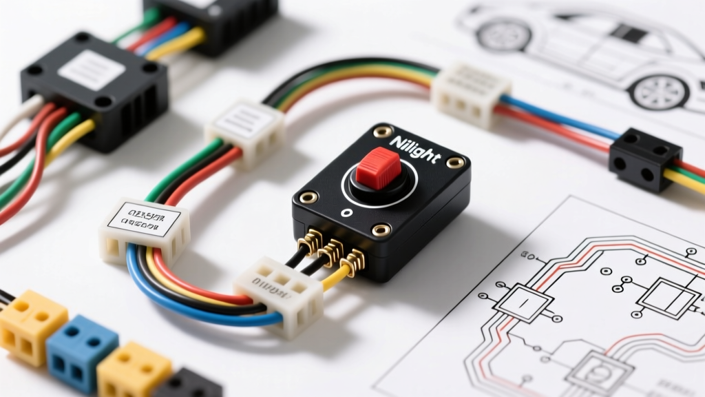
The Anatomy of a Nilight Switch Panel Failure
Nilight 5-gang and 6-gang rocker switch panels have become the de facto standard for off-road lighting, marine accessories, and overlanding builds. Utilizing standard Carling-style V-series switch bodies, these kits offer a plug-and-play harness that simplifies installation. However, the 'plug-and-play' label creates a false sense of security. When installers treat these panels as universal power distributors rather than low-current trigger interfaces, the results range from nuisance blown fuses to catastrophic electrical fires.
As an automotive electrical specialist, I frequently troubleshoot melted switch housings, backfed illumination circuits, and voltage drops in custom rigs. Below, we break down the most critical Nilight rocker switch wiring mistakes, the underlying physics of why they fail, and the SAE-compliant methods to correct them.
Mistake 1: Miswiring the 8-Pin Illumination Circuit
Most Nilight kits utilize DPST (Double Pole Single Throw) 8-pin rocker switches. The internal architecture separates the high-amperage load circuit from the low-amperage LED illumination circuit. A pervasive error is confusing the load terminals with the illumination terminals, resulting in switches that either fail to power the accessory or cause the LED indicators to remain illuminated constantly, draining the battery.
Standard 8-Pin Carling-Style Pinout Reference
| Pin Number | Function | Circuit Type | Wire Gauge (Typical) |
|---|---|---|---|
| Pin 1 | Common / Power In | Load Circuit | 14 AWG - 12 AWG |
| Pin 2 | Lower LED Ground | Illumination | 18 AWG |
| Pin 3 | Lower LED Power (Switched) | Illumination | 18 AWG |
| Pin 4 | N/C (Not Connected) | - | - |
| Pin 5 | Load Out (Accessory) | Load Circuit | 14 AWG - 12 AWG |
| Pin 6 | N/C (Not Connected) | - | - |
| Pin 7 | Upper LED Ground | Illumination | 18 AWG |
| Pin 8 | Upper LED Power (Constant 12V) | Illumination | 18 AWG |
The Fix: Never route your primary accessory load through Pins 2, 3, 7, or 8. The internal PCB traces for the LED illumination are rated for roughly 10-20 milliamps. Forcing a 5A cooling fan through the illumination pins will instantly vaporize the trace and melt the switch faceplate. Always verify pin continuity with a digital multimeter (DMM) before applying 12V power.
Mistake 2: Exceeding the 18 AWG Jumper Harness Ampacity
Nilight panels feature a pre-wired jumper harness that daisy-chains the power input (Pin 1) across all switches in the panel. This jumper wire is almost universally 18 AWG. The critical mistake occurs when an installer uses the panel to directly switch a high-draw accessory—such as a 25A air compressor or a 15A heated seat—without utilizing a secondary relay.
According to SAE J1128 standards for low-tension primary cables, 18 AWG copper wire in an engine bay environment (where ambient temperatures exceed 125°C) has a maximum continuous ampacity of roughly 10 to 14 amps. If you pull 20 amps through the 18 AWG jumper harness, the wire becomes a resistive heating element. The insulation will degrade, melt against the aluminum or plastic panel housing, and eventually cause a dead short to ground.
The Fix: Use the Nilight panel strictly as a trigger interface. The switch should only carry the coil-trigger current (typically 0.5A to 2A) for a secondary high-amperage relay located near the battery or the accessory. Run 12 AWG or 10 AWG primary wire directly from the battery (fused) to the secondary relay, and from the relay to the load.
Mistake 3: The 'Floating Ground' Backfeed Hazard
The LED indicators in these rocker switches require a dedicated ground path (Pins 2 and 7). A common shortcut is to daisy-chain the illumination grounds to the load ground, or worse, to rely on a 'floating ground' through the accessory's internal circuitry. This creates a backfeed loop.
When the switch is turned off, if the ground path is shared with an inductive load (like an LED light bar with internal capacitors or a motor), residual voltage seeks the path of least resistance. This often results in 'ghost switching,' where the switch LEDs glow dimly when turned off, or the accessory receives a trickle current that slowly depletes the vehicle's battery over a 48-hour parking period.
The Fix: Establish a dedicated, centralized ground bus bar for the switch panel illumination. Use 18 AWG tinned marine-grade wire, terminate it with a closed-ring terminal, and secure it directly to bare, unpainted chassis metal using a stainless steel bolt and star washer. Apply dielectric grease over the terminal to prevent galvanic corrosion.
Mistake 4: Oversizing the Inline ATC Fuse
Every Nilight kit includes an inline fuse holder on the main battery feed. A dangerous and frequent mistake is replacing the factory 15A or 20A blade fuse with a 30A or 40A fuse to 'stop it from blowing' when multiple switches are activated simultaneously.
Fuses do not protect the accessory; they protect the wire. If your main feed to the switch panel is 14 AWG, and you install a 40A fuse, a 35A short circuit will not blow the fuse. Instead, the 14 AWG wire will reach its thermal limit, catch fire, and burn the vehicle to the ground before the fuse element melts.
Wire Gauge to Maximum Fuse Size Chart
| Wire Gauge (AWG) | Max Fuse Size (Engine Bay) | Max Fuse Size (Cabin) |
|---|---|---|
| 18 AWG | 10A | 15A |
| 16 AWG | 15A | 20A |
| 14 AWG | 20A | 25A |
| 12 AWG | 25A | 30A |
| 10 AWG | 30A | 40A |
The Fix: Match the fuse strictly to the smallest wire gauge in the circuit run. If you require more current capacity to run multiple high-draw accessories, you must upgrade the main feed wire to the panel to 10 AWG or 8 AWG and utilize a 50A or 60A ANL/MAXI fuse at the battery terminal.
Mistake 5: Ignoring Inductive Kickback on Motor Loads
If you are wiring a Nilight switch to directly control an inductive load—such as a radiator fan, a winch solenoid, or a water pump—you are subjecting the internal switch contacts to inductive kickback. When the circuit is broken (switch turned off), the collapsing magnetic field in the motor generates a high-voltage reverse spike. This spike arcs across the switch contacts, causing pitting, carbon buildup, and eventual contact welding (where the switch physically fuses in the 'ON' position).
The Fix: Never switch inductive loads directly through the panel. Always use the switch to trigger a heavy-duty relay. For added protection, wire a flyback diode (such as a 1N5408) in reverse bias across the relay coil or the motor terminals to safely dissipate the voltage spike. For comprehensive relay wiring diagrams and diode placement, consult the the12volt.com relay reference guide.
Environmental Sealing and Termination Standards
Finally, the physical termination of the wiring harness is where moisture intrusion destroys custom switch installations. Nilight kits often include basic PVC heat shrink or vinyl crimp connectors. In off-road, marine, or convertible environments, PVC heat shrink will crack, allowing capillary action to wick moisture directly into the copper strands, leading to green rot and high resistance.
Professional Standard: Discard the included vinyl connectors. Strip the wires using a precision wire stripper to avoid nicking the copper strands. Use adhesive-lined, dual-wall 3:1 polyolefin heat shrink ring terminals. When heated, the inner adhesive layer melts and seals the wire insulation to the terminal barrel, creating a completely waterproof mechanical and electrical bond. Ensure all connections are secured with a ratcheting crimp tool calibrated for the specific AWG to achieve the correct compression ratio.