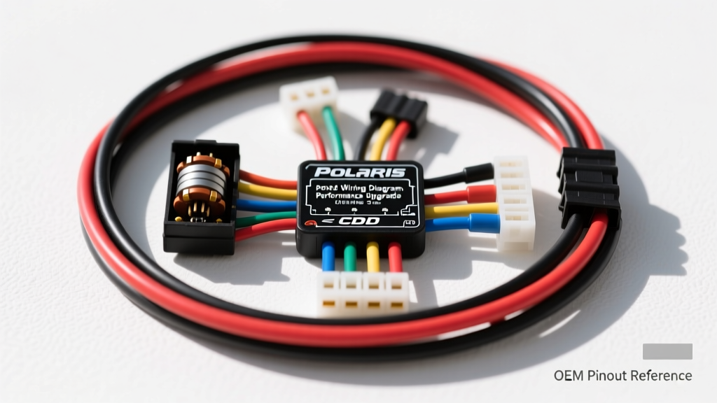
Why Upgrade Your Polaris OEM CDI?
Upgrading the Capacitor Discharge Ignition (CDI) on a Polaris Sportsman, Scrambler, or Outlaw 500 is one of the most effective modification projects you can undertake for both reliability and performance. The OEM CDI units—often manufactured by Mitsubishi or Denso for Polaris—are notorious for specific failure modes. The primary culprit is internal epoxy delamination. Due to the extreme thermal cycling of the engine bay and frequent mud or water intrusion, the potting compound cracks over time. Once compromised, moisture wicks into the thyristor circuitry, causing erratic spark timing, high-RPM misfires, or a complete no-spark condition.
Furthermore, the factory CDI imposes conservative rev limits and timing curves designed for emissions and general trail riding, not aggressive off-road racing or dune performance. By utilizing an accurate Polaris CDI wiring diagram to install an aftermarket digital ignition (such as those from Rick's Motorsport Electrics or Trail Tech), you can eliminate the factory rev limiter, optimize the spark advance curve, and drastically improve the durability of your ignition system. This guide provides the exact technical specifications, pinout translations, and fabrication steps required to execute this upgrade flawlessly.
OEM vs. Aftermarket Polaris CDI Wiring Diagram
The most critical phase of this modification project is translating the OEM Polaris harness to the aftermarket CDI pigtail. While the functions remain identical, the wire color codes and pin orientations frequently differ. The Polaris 500cc Fuji 4-stroke and the classic 500 2-stroke platforms generally utilize a 6-pin Molex-style connector at the CDI module.
Below is the definitive pinout translation table for adapting the OEM harness to a standard aftermarket 6-pin performance CDI. Always verify your specific harness with a multimeter before cutting, as mid-year production changes can occasionally swap trigger polarities.
| OEM Pin | OEM Wire Color | Circuit Function | Aftermarket Wire Color | AWG Spec |
|---|---|---|---|---|
| 1 | Red/White | Switched 12V+ (Key On) | Red | 16 AWG |
| 2 | Black | Chassis Ground | Black | 14 AWG |
| 3 | Green/White | Pulsar/Trigger Coil (+) | White/Red | 18 AWG |
| 4 | Green/Black | Pulsar/Trigger Coil (-) | White/Black | 18 AWG |
| 5 | Yellow | Stator AC Power Input | Yellow | 14 AWG |
| 6 | Pink/Black | Engine Kill / Rev Limiter | Black/White | 18 AWG |
Stator Source Coil and Pulsar Matching
An aftermarket CDI is only as good as the stator feeding it. The CDI requires raw AC voltage from the stator's dedicated source coil (not the lighting coils) to charge its internal capacitor. Before installing your new CDI, you must verify the health of your Polaris stator.
Source Coil Resistance Testing
Disconnect the stator plug and set your digital multimeter to Ohms (Ω). Measure the resistance across the Yellow source coil wire and the engine ground. According to Rick's Motorsport Electrics testing protocols, a healthy Polaris 500 Fuji stator source coil should read between 480 Ω and 560 Ω at 68°F (20°C). If your reading is below 400 Ω or shows an open circuit (OL), the source coil is shorted or broken, and the stator must be replaced or rewound before the CDI upgrade will function.
Pulsar Coil Air Gap Verification
The trigger coil (pulsar) dictates the exact moment the CDI fires the ignition coil. If you are reinstalling the flywheel or replacing the pulsar during this project, the air gap between the pulsar magnet and the flywheel reluctor must be set precisely. Use a non-magnetic brass feeler gauge to set the gap to 0.010" - 0.015" (0.25 - 0.38mm). A gap wider than 0.020" will result in a weak trigger signal, causing the CDI to fail to fire during low-RPM cranking.
Harness Fabrication: Upgrading AWG and Connectors
The OEM Polaris wiring harness utilizes thin 18 AWG and 20 AWG wires to save weight and manufacturing costs. For a high-performance ignition upgrade, this creates unnecessary resistance and voltage drop, particularly on the ground and AC power circuits. When splicing your aftermarket CDI into the chassis harness, follow these fabrication standards:
- Wire Gauge Upgrades: Replace the OEM Black (Ground) and Yellow (AC Power) wires with 14 AWG stranded copper wire. This aligns with the SAE J1128 standard for low-tension primary cables, ensuring minimal voltage drop under the high-current demands of rapid capacitor charging.
- Soldering and Sealing: Never use crimp butt-connectors for ignition circuits. Vibration will cause micro-fractures in the crimp barrel. Strip the wires, twist them, and apply rosin-core solder. Seal every splice with 3:1 shrink ratio adhesive-lined marine heat shrink. The internal polyolefin adhesive melts and creates a waterproof seal, preventing the green corrosion that plagues OEM Polaris harnesses.
- Connector Upgrades: Cut off the brittle OEM Molex connector. Terminate the harness side with a Deutsch DT series 6-pin receptacle (Part # DT06-6S). Deutsch connectors feature silicone rear seals and beryllium-copper contacts that resist vibration-induced fretting corrosion, making them the gold standard for off-road electrical modifications.
Bypassing Factory Safety Interlocks
One of the most common reasons for upgrading the CDI on a Polaris Sportsman or Scrambler is to eliminate the factory safety interlocks that artificially limit engine RPM. On OEM machines, the Pink/Black (Kill/Limiter) wire routes through a complex network including the neutral switch, the Reverse Override Module (ROV), and the thumb throttle safety switch.
If your modification project involves building a dedicated race quad or dune machine, you can bypass these limiters. To do this safely without leaving the engine unable to shut off:
- Trace the OEM Pink/Black wire back to the first junction where it meets the neutral and reverse switches.
- Cut the wire, isolating the CDI side from the chassis safety switch side.
- Install a heavy-duty, weather-sealed toggle switch (rated for at least 5A) on the handlebars.
- Wire one side of the toggle switch to a clean Switched 12V+ source (Red/White), and the other side to the CDI-side Pink/Black wire.
- When the toggle switch is closed, it sends 12V to the CDI's kill circuit, safely grounding the ignition and stopping the engine. This completely removes the factory RPM limits while retaining a reliable manual kill switch.
Note: Bypassing safety interlocks is intended for closed-course competition vehicles only. Retaining factory safety switches is required for trail riding and street-legal UTV/ATV configurations.
Final Testing and Torque Specifications
Before reassembling the plastics and taking the machine to the trail, perform a dynamic spark test. Remove the spark plug, reconnect it to the ignition coil wire, and ground the plug threads to the cylinder head. Crank the engine; you should see a thick, bright blue spark. A weak, orange spark indicates a failing ignition coil or inadequate stator AC voltage.
For advanced diagnostics, use a Digital Voltage Adapter (DVA) to measure the stator's peak AC voltage while cranking. A healthy Polaris 500 stator should produce a minimum of 100V Peak while cranking and exceed 200V Peak at idle. If the DVA reading is low, your stator is failing, or the flywheel magnets have weakened due to heat exposure.
Hardware Torque Specs
Proper fastener torque is vital to prevent the flywheel from shearing its Woodruff key, which would instantly destroy your ignition timing. Refer to the official Polaris ATV Service Manuals for your specific year, but general specifications for the 500cc platform include:
- Flywheel/Rotor Nut: 45 - 50 ft-lbs (61 - 68 Nm). Apply a drop of Blue Loctite (243) to the crankshaft threads.
- CDI Mounting Bolts: 84 in-lbs (10 Nm). Ensure the rubber isolation grommets are in place to prevent chassis vibration from cracking the CDI's internal circuit board.
- Stator Mounting Bolts: 84 in-lbs (10 Nm). Use a thread-locking compound to prevent the stator from shifting and altering the air gap.
By meticulously following this Polaris CDI wiring diagram and upgrade protocol, you will eliminate the weak points of the factory ignition system, resulting in a crisper throttle response, higher RPM ceiling, and an electrical system capable of surviving the harshest off-road environments.