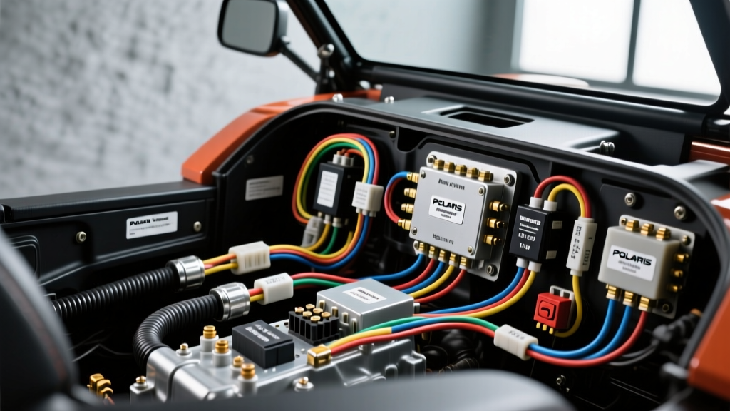
The Hidden Dangers in Your Polaris Ranger Wiring Diagram
Installing aftermarket accessories on a modern side-by-side requires more than just connecting a red wire to a positive terminal. When consulting a Polaris Ranger wiring diagram, many off-road enthusiasts fail to realize that vehicles like the Ranger 1000 XP and 900 XP utilize complex multiplexed CAN bus systems alongside traditional 12V analog circuits. Misinterpreting a schematic or taking shortcuts during installation can lead to catastrophic electrical failures, melted harnesses, or a fried Engine Control Unit (ECU). As an automotive electrical specialist, I have traced countless parasitic draws and short circuits back to improper accessory installations. This guide outlines the five most common mistakes made when reading and executing a Polaris Ranger wiring diagram, complete with safety warnings and technical corrections.
Mistake #1: Tapping into CAN Bus or ECU Switched Circuits
The most severe mistake occurs when installers look for a "switched 12V" source to trigger a relay and accidentally tap into the ECU or instrument cluster harness. On the Polaris Ranger 1000 XP, the main ECU connector features pins dedicated to the CAN High (typically Pin 14, Yellow/Red) and CAN Low (Pin 15, Yellow/White) data lines. These operate at 2.5V to 3.5V. If you use a test light or a standard multimeter on a low-impedance setting, you might mistakenly identify a 5V reference wire or a CAN signal wire as a low-amperage 12V source.
Connecting a standard 12V relay coil (which draws roughly 150mA to 300mA) to a 5V ECU reference pin will instantly overload the ECU's internal driver transistor, permanently destroying the computer. The Fix: Never probe ECU pins with a standard test light. Always use a high-impedance digital multimeter and an automotive logic probe. For switched 12V triggers, use the dedicated accessory bus bar located under the hood or install an Add-A-Circuit fuse tap on a non-critical circuit like the 12V auxiliary power outlet (cigarette lighter) fuse.
Mistake #2: Undersizing AWG for High-Draw Accessories
ATV and UTV electrical systems are highly susceptible to voltage drop due to the length of the wire runs from the front-mounted battery or bus bar to the rear of the vehicle. Many installers use 14 AWG wire for a 10A LED light bar mounted on the rear roll cage because "14 AWG is rated for 15 amps." However, according to the SAE J1128 standard for Low Tension Primary Cable, wire ampacity drops significantly over distance due to resistance and under-hood ambient heat.
Running 14 AWG wire 15 feet to draw 10A will result in a voltage drop of nearly 1.5V, leaving your light bar with only 10.5V and causing premature failure or flickering at idle RPMs. Always calculate voltage drop based on the total round-trip length (positive and negative runs).
Polaris Ranger Accessory Wiring Matrix
| Accessory | Max Draw | Min AWG Size (15ft Run) | Wire Route | Connector Type |
|---|---|---|---|---|
| Roof LED Light Bar | 12A | 12 AWG | Along factory harness channel | Deutsch DT (2-Pin) |
| Heated Grips / Seats | 6A | 14 AWG | Through steering column grommet | Deutsch DTM (2-Pin) |
| Winch Contactor | 150A+ Peak | 2 AWG or 4 AWG | Direct to Battery (Bypass Bus Bar) | Heavy Duty Ring Terminals |
| GPS / Radio | 3A | 16 AWG | Behind dash cluster | Weather-Pack (2-Pin) |
Mistake #3: Chassis Grounding on Powder-Coated Frames
A proper ground is just as critical as a proper power source. The Polaris Ranger frame is heavily coated in a thick, durable powder coat (typically 2 to 4 mils thick). Powder coat is an electrical insulator. Many installers strip the ground wire, wrap it around a random suspension bolt or frame tab, and tighten it down, assuming the metal-to-metal contact is sufficient. Over time, vibration and moisture cause this high-resistance connection to fail. When the primary ground fails, the accessory will attempt to backfeed its ground through the CAN bus or other sensitive 12V modules, leading to erratic dash behavior or blown ECU diodes.
The Fix: Always terminate negative wires to the factory negative bus bar located near the battery. If you must ground to the chassis, use a Dremel or sandpaper to remove the powder coat down to bare, shiny metal. Secure the ring terminal with a stainless steel bolt and a star washer to bite into the metal, and immediately coat the connection in dielectric grease or marine-grade liquid electrical tape to prevent oxidation.
Mistake #4: Using Standard Spade Connectors in High-Moisture Zones
Standard vinyl-insulated spade connectors and butt splices have no place on an off-road vehicle. The Polaris Ranger is subjected to deep water crossings, mud, and high-pressure washing. Standard connectors will wick moisture directly into the copper strands via capillary action, leading to green corrosion (copper oxide) that increases resistance and generates heat. According to TE Connectivity's specifications for Deutsch connectors, the DT series features a silicone rear grommet and front seal that provides a completely waterproof, IP68-rated seal around the wire insulation.
The Fix: Use Deutsch DT connectors for circuits up to 13A per contact (12-14 AWG wire) and Deutsch DTM connectors for circuits up to 7.5A (16-20 AWG wire). Always use the proper crimping tool to compress the contact barrel, and ensure the wire seal is crimped tightly over the wire's outer insulation jacket, not the bare copper strands.
Mistake #5: Routing Winch Contactor Power Through the Accessory Bus Bar
The factory accessory bus bar on the Polaris Ranger is typically rated for a maximum continuous draw of 30 to 40 amps total across all terminals. A standard 4,500 lb UTV winch can draw 120 to 150 amps under heavy load, with initial inrush currents spiking even higher. Wiring the main power feed for a winch contactor through the factory bus bar or a standard 30A relay will instantly melt the bus bar traces and potentially start an electrical fire in the engine bay.
The Fix: The winch contactor must be wired directly to the battery terminals using 4 AWG or 2 AWG pure copper welding cable. You must install a 200A Marine-grade ANL or Mega Fuse within 8 inches of the positive battery terminal. The trigger wire for the contactor (which only draws 2-3 amps) can safely be routed to a switched 12V source via a standard 4-pin ISO relay and a dash-mounted rocker switch.
Standard ISO Relay Wiring for Ranger Accessories
When your Polaris Ranger wiring diagram requires adding a relay for high-draw accessories (like driving lights or a fuel pump), use the standard ISO mini relay pinout:
- Pin 30 (Common): Connect to 12V+ from the accessory bus bar (with an inline fuse rated for the accessory).
- Pin 87 (Normally Open): Connect to the positive terminal of your accessory.
- Pin 85 (Coil Ground): Connect to the negative bus bar or a verified bare-metal chassis ground.
- Pin 86 (Coil Trigger): Connect to your dash switch, which receives switched 12V from the ignition circuit.
Note: Always install a flyback diode across pins 85 and 86 (stripe facing Pin 86) if the accessory is controlled by a solid-state switch or the ECU, to prevent voltage spikes from destroying the trigger circuit.
Essential Safety Warnings & Best Practices
Before cutting, stripping, or crimping a single wire on your Polaris Ranger, adhere to these non-negotiable safety protocols:
- Disconnect the Battery: Always remove the negative battery terminal first before working on the electrical system to prevent accidental shorting against the frame.
- Use Marine-Grade Heat Shrink: Avoid electrical tape. Use dual-wall, adhesive-lined marine heat shrink tubing. When heated, the inner adhesive melts and creates a waterproof seal that blocks moisture migration.
- Reference the Factory Manual: Always cross-reference your work with the official Polaris Ranger Service Manual for your specific model year, as pinouts and bus bar locations can change between the 900, 1000, and EV platforms.
- Secure the Harness: Use UV-resistant zip ties or factory-style push-clips to secure new wiring. Ensure wires are routed away from the exhaust header, steering shaft, and suspension components to prevent chafing and short circuits.
By respecting the engineering behind the Polaris Ranger wiring diagram and avoiding these common pitfalls, you ensure your off-road machine remains reliable, safe, and ready for the trail.