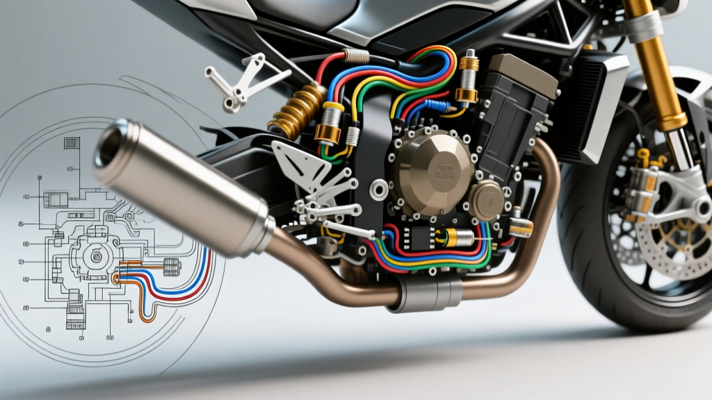
The Hidden Dangers of Free Kawasaki Wiring Diagrams
Searching for free Kawasaki wiring diagrams is a common first step for DIY mechanics tackling everything from a simple tail tidy installation to a full stator replacement on a Ninja 650 or ZX-6R. However, relying on unverified, generic, or outdated schematics found on forums and third-party sites is one of the leading causes of catastrophic electrical failures in the Kawasaki community. A misinterpreted wire color code or an overlooked ground pin can instantly fry a $1,200 Denso ECU or cause a harness fire.
As an automotive and motorcycle electrical specialist, I have traced countless parasitic draws and melted connectors back to a single error made while following a poorly translated or incorrect year-model diagram. Below, we break down the most critical mistakes, safety warnings, and technical traps associated with using free Kawasaki wiring diagrams, ensuring your electrical modifications are safe, reliable, and up to factory specifications.
Mistake 1: Confusing Kawasaki JIS Color Codes with SAE Standards
The most frequent error occurs when mechanics apply Society of Automotive Engineers (SAE) color assumptions to Japanese Industrial Standards (JIS) wiring. While the SAE J1128 Standard defines standard color codes for low-tension primary cables in North America, Kawasaki utilizes a specific JIS-based nomenclature that relies heavily on base colors with tracer stripes.
Many free diagrams will list a wire as 'Black/Yellow'. A novice might assume this means a black wire twisted with a yellow wire, or they might misidentify a brown wire as black due to age and heat discoloration. In Kawasaki factory manuals, 'BK/Y' strictly means a solid black wire with a yellow longitudinal tracer stripe. Furthermore, Kawasaki abbreviates colors differently than domestic manufacturers (e.g., 'L' for Light Blue, 'P' for Pink, 'Br' for Brown).
Kawasaki Factory Wire Color Abbreviation Chart
| Abbreviation | Base Color | Common Application (Ninja / Z Series) |
|---|---|---|
| BK | Black | Primary Chassis Ground |
| W | White | High Beam / Instrument Cluster Power |
| R | Red | Main Battery Positive (Unswitched) |
| G | Green | Left Turn Signal / CAN-Low (Late Models) |
| Y | Yellow | 3-Phase Stator Output (AC Voltage) |
| Br | Brown | Right Turn Signal / Tail Light Positive |
| O | Orange | ECU Sensor 5V Reference |
| L | Light Blue | Right High Beam / Injector Signal |
| P | Pink | Speed Sensor Signal / Diagnostic Output |
Warning: Never use a test light to pierce Kawasaki wire insulation to identify colors. Piercing the PVC/AVSS insulation introduces moisture, leading to copper oxidation and high-resistance failures inside the harness wrapper. Always back-probe the Yazaki or Sumitomo connector terminals.
Mistake 2: The Regulator/Rectifier Sense Wire Trap
Kawasaki motorcycles, particularly the Ninja 650 (EX650) and Versys 650, are notorious for stator and Regulator/Rectifier (R/R) burnouts. When users download free wiring diagrams to upgrade their failing shunt-style R/R to a modern MOSFET unit (like the FH020AA), they often use a generic 5-pin diagram that completely omits the critical 'Sense' wire found on 6-pin Kawasaki harnesses.
If you wire a 6-pin MOSFET R/R using a 5-pin free diagram, you might tie the Sense wire directly to the battery positive. This defeats the purpose of the sense wire, which is designed to measure voltage after the main harness resistance, at the ignition switch output. According to the Electrosport Tech Center, failing to connect the sense wire to a switched 12V ignition source (usually the Red/White or White/Red wire on the main harness connector) will cause the R/R to overcharge the battery at 15.5V+ or fail to regulate the stator's AC output properly, boiling the battery acid and destroying the ECU.
Stator & R/R Troubleshooting Decision Tree
- Symptom: Battery reads 12.4V at idle, but drops to 11.6V at 4,500 RPM.
- Cause: Stator open circuit or Shunt R/R thermal failure.
- Action 1: Disconnect the 3-pin Yellow stator connector. Set multimeter to AC Volts.
- Action 2: Measure across Yellow pins (1-2, 2-3, 1-3). You must see 50V-70V AC at 4,000 RPM. If one pair reads 0V, the stator is burnt internally.
- Action 3: Set multimeter to Ohms (Continuity). Measure from each Yellow stator pin to the engine block. It must read 'OL' (Open Line). If it reads continuity, the stator is grounded to the case and must be replaced.
Mistake 3: ECU Ground Pin Misidentification
Modern Kawasaki fuel-injected models utilize complex Denso ECUs (often 36-pin or 48-pin configurations). Free wiring diagrams frequently simplify the ECU ground pins, grouping them into a single 'Ground' symbol. This is a massive technical error. On a Ninja 650 Denso 36-pin ECU, Pin 14 is the dedicated Sensor Ground, Pin 15 is the Power Ground, and Pin 34 is the Chassis Ground.
If a mechanic follows a simplified diagram and splices all three ground wires into a single 16 AWG wire bolted to the frame, the high-current return from the fuel injectors (traveling through the Power Ground) will create a voltage drop on the Sensor Ground. This causes the ECU to read erratic Throttle Position Sensor (TPS) and Manifold Absolute Pressure (MAP) voltages, resulting in lean hesitation, backfiring, and erratic idle speeds. Always run dedicated 14 AWG ground wires from the ECU connector directly to the manufacturer's designated star-ground point on the frame, bypassing any secondary harness splices.
Mistake 4: Ignoring Wire Gauge (AWG) Specifications
Most free Kawasaki wiring diagrams do not specify the American Wire Gauge (AWG) or the metric cross-sectional area (mm²) of the wires. They only show the circuit path. Replacing a melted main harness wire with whatever scrap wire is in your garage is a severe fire hazard. Kawasaki uses AVSS (Automobile Vinyl Thin Wall) wiring, which has a thinner insulation profile but higher heat tolerance than standard marine wire.
Kawasaki Main Circuit AWG Requirements
| Circuit | Factory Fuse Rating | Minimum Required AWG (Copper) | Failure Mode if Undersized |
|---|---|---|---|
| Battery to Starter Solenoid | None (Main Cable) | 8 AWG | Voltage drop, slow cranking, melted ring terminal. |
| Main Harness Power (Red) | 30A Main Fuse | 10 AWG | Insulation melting, parasitic draw, harness fire. |
| ECU / Fuel Injection | 15A | 14 AWG | Injector pulse width fluctuation, ECU reset. |
| Cooling Fan Motor | 10A | 16 AWG | Fan relay overheating, engine thermal shutdown. |
| ABS Module / CAN-Bus | 10A | 18 AWG (Twisted Pair) | CAN-bus signal degradation, ABS fault codes. |
Critical Safety Warnings for Kawasaki Electrical Work
Before cutting, splicing, or testing any circuit based on a free Kawasaki wiring diagram, adhere to these non-negotiable safety protocols:
- Disconnect the Battery Negative First: Always remove the negative (-) battery terminal before probing ECU or airbag/crash sensor connectors (on late-model ZX-10R or Ninja H2 models). Back-probing a live CAN-bus wire with a multimeter probe can short the 5V logic board inside the ABS/IMU module.
- Beware of Ghost Voltages on CAN-Bus: Late-model Kawasakis use a CAN-bus system (Green and Green/White twisted pair). Because these are high-speed digital data lines, a standard high-impedance digital multimeter may read 'ghost voltages' (e.g., 2.5V to 4.5V fluctuating). Do not attempt to 'fix' this voltage; it is normal data transmission. Use an oscilloscope for CAN-bus diagnostics.
- Use Dielectric Grease on Multi-Pin Connectors: Kawasaki's main harness-to-sub-harness connectors (often 18-pin or 24-pin Sumitomo HM series) are located near the steering neck where water ingress is common. Always apply a silicone-based dielectric grease to the rubber seals and terminal faces before mating. Never use petroleum-based grease, which swells and destroys the rubber weatherpack seals.
- Verify the Exact Model Year: Kawasaki frequently updates harness routing and pinouts mid-generation. A 2012 Ninja 650 diagram is vastly different from a 2017 Ninja 650 diagram due to the introduction of the slipper clutch, ride-by-wire throttle, and updated ABS modules. Always cross-reference your specific VIN with the Kawasaki Official Service Manuals portal before making permanent cuts.
Conclusion
Free Kawasaki wiring diagrams are excellent for gaining a general understanding of a circuit's flow, but they should never replace factory-verified documentation when executing physical repairs. By respecting JIS color codes, properly wiring R/R sense circuits, maintaining dedicated ECU grounds, and strictly adhering to AWG specifications, you can avoid the devastating electrical failures that plague the DIY motorcycle community. When in doubt, invest in the official factory service manual for your specific VIN—it is the cheapest insurance policy you can buy for your motorcycle's electrical system.