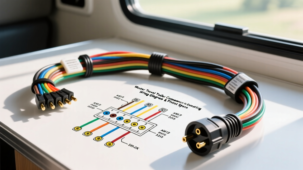
Understanding the Travel Trailer Camper Wiring Diagram Architecture
When referencing a travel trailer camper wiring diagram, technicians and DIYers must recognize that the RV electrical system is a tripartite architecture. It encompasses the exterior 7-way umbilical connection, the 12V DC interior branch circuits, and the 120V AC shore power distribution. Unlike standard automotive harnesses, travel trailer wiring must endure high-vibration environments, extreme thermal cycling, and significant voltage drop over long wire runs. This technical specification reference details the exact wire gauges, color codes, pin configurations, and torque specifications required to build, repair, or diagnose modern travel trailer electrical systems in accordance with RVIA (Recreational Vehicle Industry Association) standards.
7-Way RV Blade Connector: Pinout and Wire Gauge Specifications
The exterior 7-way blade connector is the primary interface between the tow vehicle and the travel trailer. While SAE J560 defines heavy-duty commercial 7-pin layouts, travel trailers utilize the RVIA standard 12V color code matrix. Misinterpreting these standards is the leading cause of blown tow vehicle fuses and trailer brake failures. Below is the definitive pinout specification for the standard RV 7-way plug (viewed from the wiring side of the male plug).
| Pin Position | Function | RVIA Wire Color | Min. AWG Size | Overcurrent Protection |
|---|---|---|---|---|
| Pin 1 (Top Left) | Left Turn / Stop Lamp | Yellow | 12 AWG | 20A Auto-Reset CB |
| Pin 2 (Bottom Left) | Reverse Lamps / Aux | Black | 12 AWG | 15A Fuse |
| Pin 3 (Center) | Chassis Ground Return | White | 8 AWG | N/A (Direct Bond) |
| Pin 4 (Top Right) | 12V Aux / Battery Charge | Red | 10 AWG (6 AWG Recommended) | 30A or 40A CB |
| Pin 5 (Bottom Right) | Right Turn / Stop Lamp | Green | 12 AWG | 20A Auto-Reset CB |
| Pin 6 (Top Center) | Tail / Marker / License | Brown | 12 AWG | 20A Auto-Reset CB |
| Pin 7 (Bottom Center) | Electric Trailer Brakes | Blue | 10 AWG | 30A Auto-Reset CB |
Expert Note on Pin 4 (12V Aux): While 10 AWG is the minimum RVIA requirement for the 12V auxiliary charge line, voltage drop over a 25-foot umbilical cord often results in less than 12.0V reaching the trailer battery. For optimal alternator charging, upgrade the tow vehicle and trailer Pin 4 circuits to 6 AWG stranded copper, protected by a 40A MIDI fuse.
12V DC Power Distribution Panel (PDP) Branch Circuits
Inside the travel trailer, the 12V DC system originates at the Power Distribution Panel (PDP), commonly manufactured by WFCO or Progressive Dynamics. The PDP receives bulk 12V power from the battery via a 30A or 40A reverse-polarity fuse block. Branch circuits are then protected by standard ATO/ATC blade fuses. When modifying a travel trailer camper wiring diagram to add accessories like solar charge controllers, inverters, or CPAP machines, you must adhere to strict ampacity derating curves.
Appliance Load and Wire Sizing Matrix
| Appliance / Circuit | Max Continuous Draw | Required Wire AWG | Fuse Rating | Terminal Torque Spec |
|---|---|---|---|---|
| Interior LED Lighting | 5A | 14 AWG | 10A | 12 in-lbs |
| Water Pump | 10A | 12 AWG | 15A | 15 in-lbs |
| 12V Fridge (Compressor) | 12A (Startup 18A) | 10 AWG | 20A | 20 in-lbs |
| Slide-Out Motor | 25A | 8 AWG | 30A | 25 in-lbs |
| Electric Awning | 15A | 10 AWG | 20A | 20 in-lbs |
When terminating stranded copper wire at the PDP bus bars, always use ferrule crimps or closed-ring terminals. Inserting bare stranded wire directly into set-screw terminal blocks causes strand fraying, leading to high-resistance hot spots and potential DC arcing fires.
120V AC Shore Power and Converter Integration
The 120V AC system in a travel trailer typically enters via a 30-amp TT-30R receptacle. It is critical to note that the TT-30 standard is strictly 120V (Hot, Neutral, Ground), unlike the 50-amp 14-50R standard which provides 120/240V split-phase power. The AC mains feed directly into the AC distribution breaker box, which also houses the 120V AC input for the onboard power converter/charger.
The power converter (typically 45A to 65A) steps down 120V AC to 13.6V DC to power the DC branch circuits and charge the house battery. The DC output of the converter must be wired to the PDP using a minimum of 6 AWG wire for runs under 10 feet, and 4 AWG for runs exceeding 10 feet, to prevent the converter from triggering its internal low-voltage thermal shutdown.
Grounding Topologies and Chassis Bonding
A critical failure point in many aftermarket travel trailer camper wiring diagrams is improper chassis bonding. The RV electrical system relies on a unified ground plane. The white ground wire from the 7-way plug must bond directly to the travel trailer's steel chassis using a star washer and a self-tapping bolt, torqued to 15 ft-lbs to bite through the powder coating. Furthermore, the DC negative bus bar inside the PDP must be bonded to this same chassis ground point using a minimum 8 AWG green or bare copper wire. Failure to establish this equipotential bonding can result in stray 12V DC currents traveling through the trailer's skin, causing rapid galvanic corrosion of the aluminum exterior panels.
Diagnostic Troubleshooting: Voltage Drop and Parasitic Draws
When diagnosing issues using a travel trailer camper wiring diagram, technicians must look beyond simple continuity testing. High resistance connections often pass a standard multimeter continuity test but fail under load. Always perform a voltage drop test across the 7-way plug pins while the circuit is under load.
Step-by-Step Voltage Drop Diagnostic
- Step 1: Set the multimeter to DC Volts. Connect the black lead to a known good chassis ground on the tow vehicle.
- Step 2: Activate the circuit under test (e.g., Pin 7 Electric Brakes) via the tow vehicle controller.
- Step 3: Probe the corresponding pin on the trailer side of the 7-way plug with the red multimeter lead.
- Step 4: A voltage drop greater than 0.5V indicates high resistance in the umbilical cord, the tow vehicle wiring, or the connector pins. Clean the brass pins with contact cleaner and apply dielectric grease to prevent oxidation.
For comprehensive standards on low-tension primary cable insulation and thermal ratings, refer to the SAE J1128 Low Tension Primary Cable Standard. Additionally, the Recreational Vehicle Industry Association (RVIA) provides the governing ANSI/RVIA LV standards for all low-voltage RV applications. For practical application guides and adapter wiring, etrailer.com's Wiring FAQ remains an excellent field reference for cross-referencing OEM harness variations.