The Hubbard Climate Effect: Why Local Automotive Wiring Fails
When tackling auto electrical repair Hubbard drivers face a unique set of environmental challenges. Nestled in Mahoning County, Hubbard experiences severe freeze-thaw cycles and heavy applications of calcium chloride and magnesium chloride road salts during the winter. These aggressive de-icing chemicals don't just rust your vehicle's frame; they wreak havoc on your electrical system. When salt-laden slush is kicked up into the engine bay and wheel wells, it accelerates galvanic corrosion inside standard vinyl-insulated butt connectors and exposed splices.
For beginners stepping into DIY automotive wiring, understanding this environmental factor is crucial. A standard crimp that might last ten years in a dry, arid climate will often develop high-resistance copper oxide (the dreaded 'green crust') within two winters in Northeast Ohio. This guide breaks down the fundamental, beginner-friendly wiring repair techniques you need to create permanent, weather-sealed connections that can survive Hubbard's harshest road conditions.
Essential Tools for Beginner Wire Repair
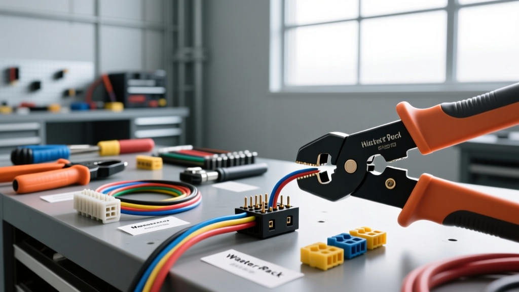
Before cutting your first wire, you need the right tools. The most common beginner mistake is using cheap, non-ratcheting crimpers that merely smash the terminal onto the wire, leaving microscopic air gaps where moisture and oxygen will immediately begin oxidizing the copper.
- Ratcheting Wire Crimper: A ratcheting crimper ensures a consistent, gas-tight deformation. The tool will not release until the exact pressure required for a specific AWG (American Wire Gauge) barrel is achieved.
- Precision Wire Strippers: Avoid generic pliers that nick the copper strands. Use automatic wire strippers with gauge-specific stops to preserve the copper's structural integrity.
- Adhesive-Lined Heat Shrink: Standard electrical tape is strictly forbidden for permanent repairs. You must use marine-grade, dual-wall heat shrink with a 3:1 shrink ratio and an internal polyamide sealant that melts at approximately 120°C (248°F).
- Heat Gun: A lighter or match will scorch the tubing and fail to activate the internal adhesive evenly. Use a dedicated heat gun with a deflector nozzle.
AWG Sizing and Standard Automotive Wire Color Codes
Matching the correct wire gauge to the circuit's amperage draw is a non-negotiable rule in auto electrical repair. Using a wire that is too thin will result in excessive voltage drop, overheating, and potentially a melted harness or fire. According to the SAE J1128 standard for Low Tension Primary Cable, automotive wire is sized to handle specific current loads while accounting for the heat generated inside engine bays.
Below is a quick-reference chart for common automotive circuits, including standard General Motors (GM) wire color codes frequently found in vehicles driven around the Hubbard area.
| AWG Size | Insulation Barrel Color | Typical Automotive Circuit | Max Ampacity (Engine Bay) | Common GM Wire Color Code |
|---|---|---|---|---|
| 18 - 16 AWG | Red | Tail lights, dash illumination, ECU sensors | 10 - 15 Amps | Brown (Park/Tail), Dark Green (Right Turn) |
| 14 AWG | Blue | Headlights, horn relays, fuel pump | 15 - 20 Amps | Light Blue (High Beam), Tan (Low Beam) |
| 12 - 10 AWG | Yellow | Power windows, blower motors, fog lights | 20 - 30 Amps | Orange (Battery Feed), Black (Ground) |
| 8 AWG | N/A (Usually Black/Red) | High-power amplifiers, main alternator feeds | 40 - 50 Amps | Red (Main Power) |
Step-by-Step: The Perfect Adhesive-Lined Heat Shrink Crimp
Creating a waterproof, vibration-resistant splice is the core skill of any DIY auto electrical repair. Follow these steps to ensure your repair outlasts the original factory harness.
Step 1: Measure and Strip
Cut out the damaged section of the wire. Select the correct gauge heat shrink butt connector (e.g., Blue for 16-14 AWG). Strip exactly 1/4 inch (6mm) of insulation from both wire ends. Do not twist the exposed copper strands; leave them straight and parallel so they slide smoothly into the connector's copper barrel.
Step 2: The Gas-Tight Crimp
Insert the first wire into the connector until the insulation rests flush against the internal metal stop. Place the connector into the correct cavity of your ratcheting crimper (aligning the color-coded cavity with the barrel). Squeeze the handles until the ratchet clicks and releases. This cold-welds the copper barrel to the wire strands, creating a gas-tight seal that physically blocks oxygen from causing corrosion. Repeat for the second side.
Step 3: Heat Shrinking and Sealing
Apply heat evenly using your heat gun, starting from the center of the connector and moving outward toward the wire insulation. Watch closely for the 'tell-tale' sign of a perfect seal: a small bead of melted polyamide adhesive must squeeze out of both ends of the tubing. This adhesive bonds to the wire's PVC or XLPE insulation, creating a 100% waterproof barrier against Hubbard's road salt and slush.
Rescuing Corroded Delphi Weather-Pack Connectors
One of the most common issues encountered in local auto electrical repair is the failure of Delphi (now Aptiv) Weather-Pack connectors. These are the rectangular, sealed connectors heavily used in engine bay sensors, such as Oxygen (O2) sensors, Throttle Position Sensors (TPS), and transmission solenoids. When the silicone ribbed seals degrade, water enters the cavity, causing the tin-plated brass terminals to oxidize.
Symptom: Intermittent Check Engine Light (CEL), rough idle, or erratic transmission shifting that worsens during wet or snowy weather.
How to Extract and Replace Weather-Pack Pins
Never forcefully yank on a wire to remove it from a connector. You will break the internal locking tang. For the common 280-series terminals, follow this extraction method:
- Identify the Series: Confirm you are working with a 280-series (medium duty) or 150-series (micro) connector. The 280 series features wide, flat brass terminals.
- Insert the Removal Tool: Use a dedicated Delphi terminal removal tool. Slide the tool into the front (mating side) of the connector cavity, straddling the male pin or sliding over the female socket.
- Release the Tang: Push the tool in until you feel it depress the primary locking tangs (the small metal barbs that hold the terminal inside the plastic housing).
- Pull the Wire: While keeping the tool depressed, gently pull the wire from the rear of the connector. The terminal will slide out cleanly.
- Crimp and Reinsert: Crimp a new 280-series terminal and weather seal onto your wire. The insulation crimp must grab the outside of the silicone ribbed seal, not the bare wire. Push the new assembly into the cavity until you hear a distinct 'click'.
For comprehensive specifications on terminal retention forces and cavity layouts, refer to the Delphi Weather-Pack connector documentation.
Real-World Troubleshooting: The 'Green Crust' Ground Fault
If your taillights are dim, or your turn signals are flashing rapidly on one side but not the other, you likely have a ground fault. In older vehicles, General Motors and Ford often daisy-chained ground wires to a single chassis bolt (e.g., Ground G100 or G110). When road salt penetrates the ring terminal, it creates a high-resistance layer of copper oxide (green crust) between the terminal and the steel chassis.
The Fix: Do not simply add a new wire on top of the corroded one. Unbolt the ground ring terminal. Use a wire brush attached to a drill to remove all rust and paint down to bare, shiny steel. Clean the ring terminal with electronic contact cleaner. Reattach the bolt, torque it to the manufacturer's specification (usually 9-12 Nm for M6 ground bolts), and coat the entire connection in a dielectric grease, such as Nyogel 760G, to seal out oxygen and moisture.
Final Thoughts on Connector Repair
Mastering these beginner-friendly fundamentals will save you hundreds of dollars in diagnostic fees and tow truck rides. By respecting the local climate's impact on your vehicle, using ratcheting tools, and relying on adhesive-lined heat shrink and proper terminal extraction techniques, your DIY wiring repairs will be as robust as factory standards. Always verify your repairs with a digital multimeter, checking for less than a 0.1V drop across any newly repaired connection under load. For more advanced diagnostic procedures and IPC/WHMA-A-620 crimping standards, consult the IPC wiring harness guidelines.