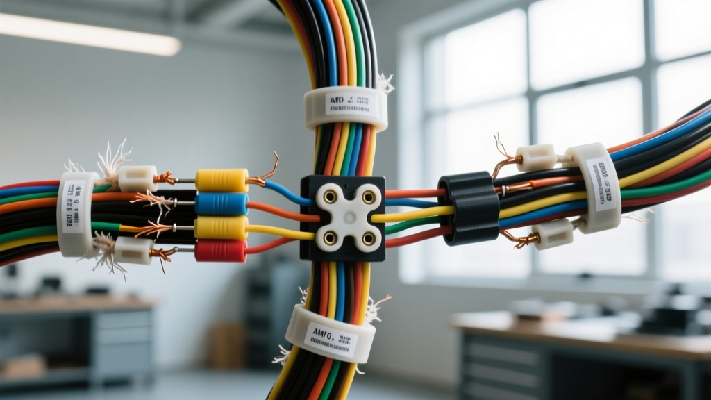
The Anatomy of a Failed Automotive Splice
In the unforgiving environment of automotive electrical systems, a compromised connection is not just an inconvenience; it is a severe fire hazard and a primary cause of parasitic battery drains. When technicians and DIYers reach for a wire splicer, they are often relying on solder seal heat shrink connectors or crimp-and-seal butt splices to restore harness integrity. However, the margin for error is razor-thin. A 12-volt automotive system can push hundreds of amps through a short circuit, and a high-resistance splice will rapidly convert that electrical energy into destructive thermal energy.
According to the IPC/WHMA-A-620 standard for cable and wire harness assemblies, a proper splice must maintain mechanical strength, electrical conductivity, and environmental sealing. Failing to adhere to these parameters results in galvanic corrosion, cold solder joints, and insulation meltdown. Below, we dissect the most critical wire splicer mistakes made in the garage and provide actionable safety warnings to protect your vehicle's electrical architecture.
5 Critical Wire Splicer Mistakes to Avoid
1. AWG Color Code Ignorance (The Mismatch Sin)
Every automotive wire splicer barrel is engineered for a specific cross-sectional area of copper. The industry-standard color coding (Red, Blue, Yellow) is not a suggestion; it is a strict mechanical requirement. A common and dangerous mistake is forcing an 18 AWG wire into a Blue (16-14 AWG) or Yellow (12-10 AWG) splicer barrel because it is the only one available in the kit.
When the crimping tool compresses an oversized barrel onto an undersized wire, the metal bites into the wire's insulation rather than the copper strands. This creates a high-resistance connection that will fail under load. Conversely, cramming a 12 AWG wire into a Red (22-18 AWG) splicer will cause the barrel to split or the copper strands to shear, leading to an immediate mechanical pull-out.
| Splicer Insulation Color | AWG Range | Metric Cross-Section | Common Automotive Application |
|---|---|---|---|
| Red | 22 - 18 AWG | 0.35 - 0.75 mm² | Sensors, CAN bus, ECU signal wires |
| Blue | 16 - 14 AWG | 1.0 - 2.0 mm² | Injectors, lighting circuits, relays |
| Yellow | 12 - 10 AWG | 3.0 - 5.0 mm² | Fuel pumps, high-amperage feeds, horn |
2. Overcooking Solder Seal Splicers
Solder seal wire splicers contain a preform ring of flux-core solder surrounded by a polyolefin heat shrink tube with an inner adhesive lining. This design relies on a precise thermal profile. The outer polyolefin jacket begins to recover at 80°C and fully shrinks at 125°C. The solder preform, however, requires approximately 165°C to melt and flow.
The Mistake: Applying a 400°C heat gun directly and intensely to the center solder ring. This causes the flux to boil off violently before the solder can properly wet the copper strands. The result is a cold, oxidized, and brittle solder joint hidden inside a shrunk tube. The Fix: Apply heat evenly from the outside edges of the splicer inward. Use a heat gun with a reflector nozzle to wrap heat around the circumference, allowing the polyolefin to shrink and seal the adhesive before the solder ring reaches its melting point.
3. Splicing High-Speed CAN Bus Networks
Modern vehicles rely on Controller Area Network (CAN) buses for critical module communication. High-speed CAN (operating at 500 kbps) requires strict adherence to a 120-ohm characteristic impedance, as defined by ISO 11898-2 physical layer requirements. Standard butt splicers and solder seal splicers introduce parasitic capacitance and an impedance discontinuity into the twisted pair.
Furthermore, CAN bus topology strictly limits "stub lengths" (the distance from the main twisted pair to a module). Introducing a bulky wire splicer and untwisting the CAN-H (often Orange/Black) and CAN-L (often Orange/Brown) wires to make the splice destroys the electromagnetic interference (EMI) cancellation of the twisted pair. Safety Warning: Never use standard wire splicers on CAN-H/CAN-L circuits. Use specialized, low-profile ultrasonic welding or factory-approved pigtail harnesses that maintain the twist rate up to the point of termination.
4. Neglecting the Environmental Seal (Adhesive vs. Non-Adhesive)
Under-hood environments are subjected to extreme thermal cycling, road salt, and high-pressure washes. A standard, single-wall heat shrink wire splicer will seal out liquid water temporarily, but it cannot stop water vapor. Through thermal expansion and contraction, the vehicle's wiring harness acts like a lung, drawing in moist air. Over time, moisture wicks through the microscopic gaps between the copper strands via capillary action, leading to green copper oxide (galvanic corrosion) deep inside the harness.
The Fix: For any repair outside the cabin, you must exclusively use dual-wall, adhesive-lined wire splicers. The inner layer consists of a thermoplastic adhesive that melts at roughly 100°C, flowing into the copper strands and completely blocking capillary wicking before the outer polyolefin jacket shrinks to form a rigid, waterproof shell.
5. Stripping Too Much Insulation (The Exposed Shoulder)
Proper wire preparation is the foundation of a reliable splice. When stripping the wire for a solder seal or crimp splicer, the bare copper must meet exactly in the center of the barrel or solder preform. If you strip too much insulation, bare copper is left exposed outside the environmental seal (the "shoulder"). This exposed copper will rapidly corrode and create a path for moisture to enter the harness. If you strip too little, the wire insulation enters the solder ring, preventing the solder from wetting the copper and resulting in a high-resistance cold joint. Strip lengths should generally be between 5mm and 7mm depending on the specific splicer manufacturer's specifications.
Forbidden Circuits: Where Splicers Are Strictly Prohibited
While a high-quality, adhesive-lined wire splicer is suitable for 80% of automotive accessory and lighting repairs, certain safety-critical and high-current circuits strictly forbid splicing. Adhering to SAE J1128 standards for automotive cable performance means recognizing when a harness must be replaced rather than repaired.
- Supplemental Restraint Systems (Airbags/SRS): SRS circuits are typically identified by yellow connectors and yellow wiring looms. These circuits operate on extremely low-voltage squib signals and rely on precise resistance monitoring (usually between 2.0 and 3.0 ohms). A spliced connection can introduce enough micro-resistance to trigger an airbag fault code or, worse, fail to deploy the airbag during a collision. Never splice SRS wiring; always replace the harness or use factory-approved, gold-plated pigtail connectors.
- High-Current Continuous Loads (EFI Pumps, Alternator Feeds): Circuits that draw continuous high amperage (e.g., a 15A+ fuel pump feed on a modern direct-injection engine) generate significant ambient heat. Splices introduce a point of higher resistance, which generates localized heat. In enclosed spaces like a fuel tank sending unit or an engine bay loom, this localized heat can degrade the surrounding wire insulation, leading to a dead short and a potential fuel fire.
- Coaxial and Shielded Audio Cables: Splicing destroys the braided shielding of coaxial cables used for GPS antennas, backup cameras, and premium amplifier signals, resulting in severe electromagnetic interference and signal loss.
Final Verification: The Pull-Test Standard
A visual inspection is not enough to verify a wire splicer connection. Professional automotive electricians verify crimp-and-seal splices using a mechanical pull-test. According to IPC-A-620 guidelines, an 18 AWG wire splicer connection must withstand a minimum pull force of 15 lbf (67 N) without the wire slipping from the barrel. A 12 AWG connection must withstand 35 lbf (155 N). If the wire pulls out, the crimping tool's die was worn, the wrong color splicer was used, or the wire was stripped improperly. Always perform a gentle but firm pull-test on both sides of the splicer before applying heat shrink, and always route the repaired wire away from sharp metal edges and exhaust components to ensure long-term harness reliability.