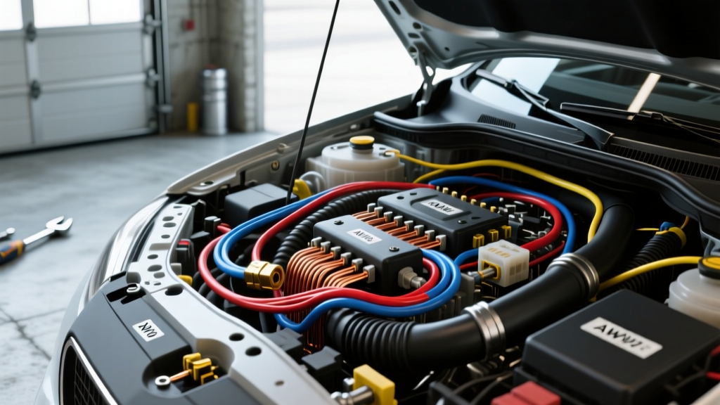
Auto Electrical Repair Yorktown: Navigating Coastal Wiring Challenges
When performing auto electrical repair, Yorktown’s unique coastal environment along the York River and Chesapeake Bay introduces severe variables that standard inland wiring guides ignore. High ambient salinity, aggressive humidity, and extreme temperature cycling rapidly expose marginal wiring practices. At AutoFlowWire, we analyze field failures from coastal Virginia to bring you this definitive guide on common connector mistakes, AWG sizing errors, and critical safety warnings. Whether you are repairing a CAN bus harness on a 2018 Ford F-150 or restoring the lighting circuit on a classic Chevrolet C10, avoiding these specific pitfalls is non-negotiable for long-term reliability.
Mistake #1: Relying on PVC Electrical Tape for Moisture Sealing
The Danger: Capillary Action and Copper Oxidation
Many DIYers and inexperienced technicians wrap butt splices in standard PVC electrical tape, assuming it provides a waterproof seal. In Yorktown's salt-heavy air, this is a catastrophic error. PVC tape relies on surface tension and adhesive tack, both of which degrade rapidly under hood temperatures exceeding 105°C (221°F). More importantly, PVC tape fails to prevent capillary action—the process where moisture wicks between the wire strands and the adhesive, traveling inches into the harness. This leads to internal copper oxidation (green verdigris), increasing resistance and causing intermittent voltage drops in critical 5-volt reference circuits like the Throttle Position Sensor (TPS).
The Correction: Adhesive-Lined Polyolefin Heat Shrink
For any splice exposed to the elements, you must use dual-wall, adhesive-lined heat shrink tubing with a 3:1 or 4:1 shrink ratio. When heated, the inner layer of thermoplastic adhesive melts and flows between the wire strands, completely blocking capillary action and creating a hermetic seal. Always strip the wire precisely so the bare copper is fully enclosed within the shrink tube, leaving no exposed strand gaps.
Mistake #2: Undersizing AWG for High-Current Accessory Runs
The Danger: Voltage Drop and Thermal Runaway
Adding off-road lighting, winches, or high-amperage audio amplifiers requires precise wire gauge calculations. A common mistake is sizing wire based solely on ampacity (the maximum current before the insulation melts) while ignoring voltage drop over long harness runs. According to SAE J1128 standards for low-voltage battery cables, a 10 AWG wire might safely carry 30 amps in a short 2-foot jumper, but running that same 10 AWG wire 15 feet from the battery to the rear of a Crew Cab truck will result in a severe voltage drop.
For critical ECU sensors, a voltage drop exceeding 3% (0.36V on a 12V system) can trigger phantom diagnostic trouble codes (DTCs). For lighting and winches, a 10% drop causes dimming and excessive heat generation at the terminal crimps.
AWG Sizing & Voltage Drop Reference Chart (12V System)
| Wire Gauge (AWG) | Max Amps (Chassis Wiring) | Max Run Length for 3% Drop @ 15A | Typical Application |
|---|---|---|---|
| 18 AWG | 6A | 3.5 Feet | LED Marker Lights, ECU Sensor Signals |
| 16 AWG | 10A | 5.5 Feet | Horn Relays, Interior Dome Lights |
| 14 AWG | 15A | 9.0 Feet | Fuel Pump Circuits, Headlight Low Beam |
| 12 AWG | 20A | 14.0 Feet | Power Windows, Cigarette Lighter Sockets |
| 10 AWG | 30A | 22.0 Feet | ABS Module Power, High-Amperage Cooling Fans |
| 8 AWG | 50A | 18.0 Feet (at 40A) | Starter Solenoid, Inverter Feeds |
Note: Always calculate total circuit length (positive feed + ground return path) when determining voltage drop.
Mistake #3: Improper Crimping on Metri-Pack 150 Terminals
The Danger: Stress Risers and Terminal Back-Out
When repairing modern sealed connectors, such as the Aptiv (formerly Delphi) Metri-Pack 150 series, technicians frequently misuse universal crimpers. A stamped automotive terminal features two distinct crimp zones: the wire grip (which must bite into bare copper) and the insulation grip (which must clamp the wire jacket to absorb mechanical tension).
If the wire grip is crimped over the insulation jacket, the connection will initially pass a continuity test but will fail within months due to vibration-induced fatigue. Conversely, if the insulation grip is crimped over bare copper, it acts as a stress riser, slicing the copper strands when the harness is flexed.
The Correction: Precision Die Selection
- Wire Grip Crimp: Must compress the terminal wings tightly around the bare strands without cutting them. The copper should be slightly visible at the front and back of the wire grip.
- Insulation Grip Crimp: Must wrap securely around the PVC/XLPE insulation without piercing it.
- Tooling: Use a ratcheting crimper with interchangeable dies specific to the terminal series (e.g., 0.64mm, 1.5mm, or 2.8mm widths). Never use pliers.
Mistake #4: Ignoring Galvanic Corrosion at Ground Points
The Danger: High-Resistance Grounds (HRG)
In coastal areas like Yorktown, grounding a copper ring terminal directly to a steel chassis or aluminum engine block without proper preparation invites rapid galvanic corrosion. When moisture and salt bridge the gap between dissimilar metals, an electrolytic cell forms. The less noble metal (often the zinc plating on the chassis or the aluminum block) corrodes away, creating a high-resistance ground.
A high-resistance ground on a fuel injector circuit (typically controlled by the ECU via the ground side) can cause lean fuel trims, misfires, and erratic idle. On a CAN bus network, a poor ground can shift the common-mode voltage, causing the CAN-H and CAN-L differential signals to collapse and throwing the vehicle into limp mode.
The Correction: Star Washers and Dielectric Grease
Always remove paint, powder coat, and surface rust down to bare metal using a wire brush or sanding disc. Use a SAE J1922 compliant star washer between the terminal and the chassis to bite through microscopic oxidation layers. After torquing the ground bolt (typically 10-15 Nm for M6 bolts), coat the entire terminal and exposed bare metal with a high-dielectric, lithium-based grease to displace oxygen and salt air.
Critical Safety Warnings: SRS and High-Voltage Systems
Electrical repairs extend beyond simple 12V lighting. Modern vehicles are laden with Supplemental Restraint Systems (SRS) and, increasingly, High-Voltage (HV) EV architectures. Adhering to safety protocols is mandatory.
| System Type | Visual Identifier | Safety Protocol & Warning |
|---|---|---|
| SRS (Airbags) | Yellow Loom / Yellow Connectors | Disconnect the 12V battery and wait a minimum of 15 minutes (up to 30 mins on some late-model Ford/GM vehicles) for the backup capacitors in the SDM (Sensing Diagnostic Module) to discharge. Never probe SRS circuits with a standard test light or multimeter; the internal battery of the meter can deploy the squib. |
| EV / Hybrid HV | Orange Loom / Orange Cables | Refer to SAE J2344 EV Safety Guidelines. Requires PPE (Class 0 insulated gloves rated to 1000V), an insulated rescue hook, and a CAT III or CAT IV multimeter. The service disconnect plug must be pulled, and voltage must be verified at 0V before touching any HV busbars. |
| CAN Bus Data | Twisted Pair (Often Green/White & Green) | Never pierce CAN bus wires with T-pins or test probes. Piercing the insulation breaches the twisted-pair geometry, altering the characteristic impedance (usually 60 ohms) and causing signal reflections that crash the network. |
Conclusion
Successful auto electrical repair in Yorktown—or any harsh coastal environment—requires a departure from outdated "twist-and-tape" methodologies. By adhering to SAE standards, utilizing adhesive-lined heat shrink, calculating precise voltage drops, and executing flawless terminal crimps, you ensure the vehicle's electrical architecture survives the elements. Always prioritize safety when interfacing with SRS and HV systems, and treat every ground point as a critical structural component of the circuit.