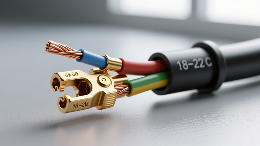
Introduction to Automotive Low Voltage Splicing
When working on modern vehicles, the term 'low voltage' generally refers to the standard 12-volt nominal electrical system, which peaks around 14.4 volts when the alternator is charging. While this voltage is not lethal to humans, the environmental demands placed on automotive wiring are extreme. A poorly executed low voltage wire splice in a 12V system will quickly succumb to engine bay vibrations, thermal cycling, moisture intrusion, and corrosive road salts. For beginners, understanding the fundamentals of a proper low voltage wire splice is the difference between a permanent repair and a recurring diagnostic nightmare.
Modern vehicles rely heavily on low-amperage, high-sensitivity signal circuits. Splicing into a 5-volt reference wire, a CAN bus network, or an oxygen sensor signal requires precision. This guide breaks down the beginner-friendly fundamentals of executing a flawless low voltage wire splice, focusing on 18 to 22 AWG (American Wire Gauge) sensor and signal wiring.
Understanding Automotive Signal vs. Power Circuits
Before picking up your wire strippers, you must identify the circuit type. Automotive low voltage circuits are broadly divided into power feeds and signal/sensor circuits. Power feeds (like headlight or fuel pump circuits) carry high current and generate heat. Signal circuits carry minimal current but demand absolute voltage integrity. A voltage drop of just 0.2 volts across a bad splice in a high-current lighting circuit might go unnoticed. That same 0.2-volt drop across a low voltage wire splice on a Mass Air Flow (MAF) sensor signal wire will trigger a Check Engine Light and cause drivability issues.
Common Low Voltage Wire Gauges and Applications
| AWG Size | Typical Application | Common Wire Colors (OEM Examples) | Splice Connector Size |
|---|---|---|---|
| 20-22 AWG | Low-current sensors, shield drains, airbag squibs | GM Sensor Ground (Black/White), Shield Drain (Bare/Green) | Red (22-18 AWG) |
| 18 AWG | Oxygen sensors, MAP sensors, CAN bus networks | Ford HS-CAN (White/Blue & White), O2 Signal (Purple) | Red (22-18 AWG) |
| 14-16 AWG | Injectors, ignition coils, interior lighting | Injector Control (Varies by cylinder), Tail lights (Brown) | Blue (16-14 AWG) |
| 10-12 AWG | Headlights, ABS module power, fuel pump feeds | Headlight High Beam (Green/White), ABS Power (Red) | Yellow (12-10 AWG) |
The Great Debate: Crimping vs. Soldering for Low Voltage
Ask any two mechanics about the best way to join wires, and you will ignite the crimping versus soldering debate. For a reliable low voltage wire splice in an automotive environment, crimping is the industry standard, governed by guidelines such as the SAE J1128 Standard for low tension primary cable and the IPC/WHMA-A-620 wire harness assembly requirements.
Why OEMs Prefer Crimping
A properly executed crimp creates a 'cold weld.' The mechanical force of a ratcheting crimper deforms the terminal barrel and the copper wire strands, breaking through surface oxides and creating a gas-tight, metal-to-metal bond. This bond remains flexible. Automotive wiring is subjected to constant vibration. A soldered joint introduces a rigid point on the wire. Right at the edge where the flexible wire meets the stiff solder wick, vibration causes microscopic fracturing, leading to a fatigue failure. Furthermore, soldering requires heat, which can melt back the insulation of modern thin-wall (TXL or GXL) automotive wire, exposing bare copper to corrosion.
When Soldering is Acceptable
Soldering is generally reserved for rigid, non-moving connections, such as attaching a terminal to a printed circuit board or repairing a rigid rear-window defroster grid. If you must solder a low voltage wire splice, use rosin-core solder (never acid-core) and ensure the joint is heavily supported by adhesive-lined heat shrink to prevent flex fatigue.
Step-by-Step: The Perfect Low Voltage Wire Splice
To execute a professional-grade splice on an 18 AWG sensor wire, you need precision wire strippers, a ratcheting crimp tool, and adhesive-lined dual-wall heat shrink butt connectors.
Step 1: Stripping Without Scoring
The most common beginner mistake is using combination pliers or dull strippers that nick the copper strands. A nick creates a stress riser, drastically reducing the wire's tensile strength and ampacity. Use a precision automatic wire stripper calibrated for the exact AWG. Strip exactly 5/16 of an inch (approx. 8mm) of insulation. The copper strands should remain perfectly parallel and untwisted before entering the terminal barrel.
Step 2: The Mechanical Crimp
Select a red, adhesive-lined butt connector rated for 22-18 AWG. Insert the first wire fully into the barrel until it hits the center stop. Using a ratcheting crimper with the correct die (usually marked 'R' or '1.5mm'), squeeze the handles until the ratchet releases. The ratcheting mechanism ensures the exact amount of compression is applied every time, preventing under-crimping (which causes pull-out) or over-crimping (which cuts the copper). Repeat for the second wire.
Step 3: Adhesive-Lined Heat Shrink Sealing
Standard PVC heat shrink is useless in an engine bay; it will crack, peel, and allow capillary action to draw moisture directly into your splice. You must use dual-wall polyolefin heat shrink, which features an inner layer of thermoplastic hot-melt adhesive. Apply heat using a dedicated heat gun (not a lighter, which creates soot and uneven heat). Heat the center of the connector first, then move outward toward the wire insulation. You know the seal is perfect when a small bead of melted adhesive squeezes out of both ends of the tubing.
The CAN Bus Exception: Maintaining the Twist
When splicing into a Controller Area Network (CAN) bus, standard splicing rules require a critical modification. CAN bus networks (like Ford's HS-CAN or GM's GMLAN) rely on differential signaling to reject Electromagnetic Interference (EMI). The wires are twisted together at a precise rate, typically one twist per inch.
When executing a low voltage wire splice on a CAN network, you must untwist the wires only as much as absolutely necessary to make the crimp (no more than 1 inch). After crimping and sealing, you must carefully re-twist the repaired section to match the factory twist rate. Failing to maintain the twist will alter the characteristic impedance of the cable, leading to signal reflection, network dropout, and U-codes (communication fault codes) in the vehicle's modules.
Troubleshooting Common Low Voltage Splice Failures
Even with careful technique, errors can occur. Use this diagnostic decision tree to identify and fix failed splices.
| Symptom | Probable Cause | Corrective Action |
|---|---|---|
| Intermittent signal drop when wiggling harness | Wire strands were nicked during stripping, or the crimp caught the wire insulation instead of bare copper. | Cut the splice out entirely. Re-strip using fresh wire ends and verify bare copper is fully visible in the barrel before crimping. |
| Green/white crust (corrosion) under heat shrink | Used single-wall PVC heat shrink, or failed to heat the adhesive-lined shrink until the sealant purged. | Remove the corroded section. Clean wire with electrical contact cleaner, crimp a new connector, and apply marine-grade dual-wall heat shrink. |
| Splice pulls apart under light tension | Used the wrong crimp die (e.g., using the Blue/16-14 AWG die on a Red/22-18 AWG terminal) or non-ratcheting pliers. | Discard the terminal. Use a calibrated ratcheting crimper and ensure the wire gauge matches the terminal color code exactly. |
| Communication codes (U-Codes) after CAN bus repair | Failed to maintain the 1-twist-per-inch ratio, or routed the splice too close to high-voltage ignition coils. | Redo the splice, strictly maintaining the factory twist rate. Ensure the repaired harness is routed at least 2 inches away from EMI sources. |
Final Thoughts on Wire Repair
Mastering the low voltage wire splice is a foundational skill for any automotive technician or DIY enthusiast. By respecting the metallurgy of cold-weld crimping, utilizing adhesive-lined environmental seals, and adhering to OEM routing and twisting specifications, you ensure that your electrical repairs will outlast the vehicle itself. Always invest in high-quality, ratcheting crimp tools and OEM-style wire repair kits to guarantee your splices meet the rigorous demands of the modern automotive environment.