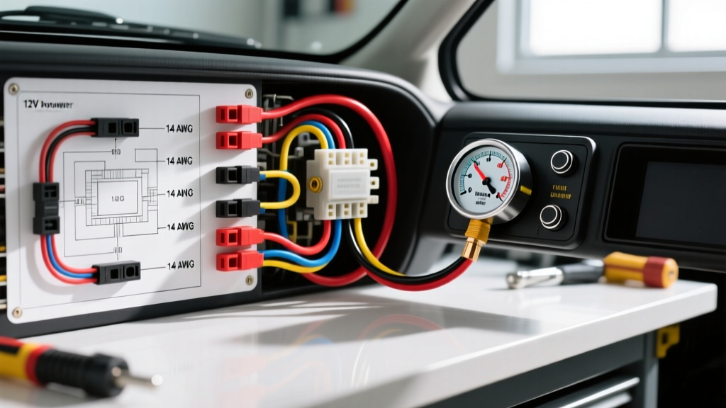
Introduction to Automotive Voltmeter Gauges
Adding an aftermarket voltmeter to your vehicle is one of the most practical electrical upgrades you can perform. Whether you are building a project car, upgrading a daily driver, or monitoring the charging system on a heavy-duty truck, knowing how to wire a voltmeter gauge correctly ensures you get accurate readings without introducing parasitic draws or fire hazards. Unlike mechanical gauges that require plumbing lines, a voltmeter only requires a simple three-wire electrical connection. However, the reliability of this setup depends entirely on your wire repair techniques, connector choices, and circuit protection.
In this beginner-friendly fundamentals guide, we will walk through the exact wiring procedures, AWG specifications, and professional crimping methods required to install a standard 12-volt analog or digital voltmeter. We will also cover modern vehicle considerations, such as avoiding CAN-bus interference when tapping into fused circuits.
Essential Tools and Materials for Gauge Wiring
Before cutting into your vehicle's wiring harness, gather the correct materials. Using household electrical supplies in an automotive environment is a primary cause of gauge failure and electrical fires. Automotive environments demand vibration-resistant, high-temperature components.
- Wire: 18 AWG GXL (cross-linked polyethylene) primary wire. GXL meets the SAE J1128 Standard for automotive low-tension primary cable, offering superior heat and abrasion resistance compared to standard PVC wire.
- Connectors: Polyolefin heat-shrink butt connectors and 10-12 AWG ring terminals with heat shrink.
- Power Tap: Add-A-Circuit (mini or standard ATO fuse tap, depending on your vehicle's fuse box).
- Tools: Wire strippers with precise AWG holes, a ratcheting crimper, a heat gun, and a digital multimeter.
- Hardware: Stainless steel ring terminal bolts, star washers, and dielectric grease.
Standard 3-Wire Voltmeter Pinout and Specifications
Most aftermarket voltmeters, including popular models referenced in AutoMeter Technical Support documentation, utilize a standard three-wire configuration. Understanding the function and required wire gauge for each pin is critical for a safe installation.
| Pin / Wire | Function | Standard Color | Recommended AWG | Connection Type |
|---|---|---|---|---|
| Pin 1 | Switched 12V Power (+) | Red | 18 AWG | Add-A-Circuit or Posi-Tap |
| Pin 2 | Chassis Ground (-) | Black | 18 AWG | Ring Terminal to bare metal |
| Pin 3 | Illumination / Dimmer | White or Orange | 20-22 AWG | Posi-Tap to dash lighting |
Note: Always verify the pinout on the specific instruction sheet provided with your gauge, as some digital models may include a fourth wire for programmable memory or data bus communication.
Step-by-Step: How to Wire a Voltmeter Gauge
Step 1: Selecting and Tapping the Switched 12V Power Source
The red power wire must be connected to a 12V source that is only active when the ignition is in the "ON" or "ACCESSORY" position. If you wire the voltmeter to a constant 12V battery source, the gauge will remain illuminated and drain your battery overnight.
For Modern Vehicles (2005+ with CAN-bus): Do not splice directly into the ignition switch harness. Modern vehicles use multiplexed data networks, and piercing a CAN-bus wire with a scotch lock can cause catastrophic module failures. Instead, locate the interior fuse panel and use an Add-A-Circuit (fuse tap). Identify a low-amperage switched fuse (such as the radio or wiper motor fuse), pull the original fuse, and insert it into the fuse tap. Add a new 3A or 5A fuse to the tap to protect your 18 AWG gauge wire. Crimp a heat-shrink butt connector to the fuse tap lead and the red gauge wire.
For Older Vehicles (Pre-OBD2): You can use a high-quality Posi-Tap connector to tap into the thick 12V accessory wire at the back of the ignition cylinder, but an inline 5A fuse holder must be soldered or crimped within 6 inches of the tap point to protect the circuit.
Step 2: Routing and Terminating the Ground Wire
The black ground wire is where most beginners make critical errors. A voltmeter measures the voltage potential between the power source and the ground source. If your ground is poor, the gauge will read artificially low and fluctuate with the turn signals or blower motor.
- Locate a Ground Point: Find a solid metal bolt on the chassis or dashboard cross-member within 18 inches of the gauge pod.
- Prepare the Surface: Use sandpaper or a wire wheel to remove all paint, powder coat, and rust from the grounding surface. You must achieve bare, shiny metal.
- Terminate the Wire: Strip 3/8 inch of insulation from the 18 AWG black wire. Crimp on an 18-22 AWG heat-shrink ring terminal (stud size #10 or #12, depending on the bolt).
- Secure the Ground: Place a star washer between the ring terminal and the bare metal to bite into the chassis. Tighten the bolt securely. Apply a dab of dielectric grease over the terminal to prevent corrosion, but never under it.
Step 3: Connecting the Dimmer/Illumination Circuit
The white or orange wire controls the gauge's backlighting. To ensure the gauge dims when you turn on your headlights, tap this wire into the vehicle's dashboard illumination circuit. Use a multimeter to probe the wires behind the headlight switch or radio harness. You are looking for a wire that shows 0V with the lights off, and scales up to 12V (or pulses via PWM on newer cars) when the headlights are turned on. Because the LED or incandescent bulb inside the gauge draws very little current (typically under 150mA), you can safely use 20 or 22 AWG wire and a micro Posi-Tap to connect to the factory illumination wire.
Professional Connector and Wire Repair Techniques
Because this installation falls under the umbrella of wire repair and connector integration, executing proper crimps is non-negotiable. The vibration of a vehicle will easily back out a poorly crimped terminal, leading to arcing or a dead gauge.
Stripping the Wire Correctly
Always use the exact hole on your wire strippers that matches your wire gauge (e.g., the 18 AWG hole for 18 AWG GXL wire). Using a hole that is too small will nick the copper strands, reducing the wire's current-carrying capacity and creating a physical weak point that will snap under engine bay vibration.
Using Polyolefin Heat-Shrink Connectors
Avoid cheap, vinyl-insulated butt connectors. Instead, use connectors with a polyolefin heat-shrink jacket and an inner layer of hot-melt adhesive. When crimping, ensure the wire insulation rests inside the shrink tube, while the bare copper is fully inserted into the metal barrel. Use a ratcheting crimper to apply uniform pressure. Once crimped, apply heat evenly with a heat gun until the tubing shrinks tightly and a small bead of adhesive squeezes out of the ends. This creates a completely waterproof, vibration-proof seal that meets OEM automotive standards.
Troubleshooting Common Voltmeter Wiring Issues
If your gauge is not behaving as expected after installation, refer to this diagnostic decision tree before assuming the gauge is defective.
| Symptom | Probable Cause | Diagnostic Fix |
|---|---|---|
| Gauge reads 0V or stays completely dead. | Blown inline fuse or no switched power. | Test the red wire with a multimeter. If 0V, check the Add-A-Circuit fuse and ensure it is seated in a switched slot. |
| Gauge reads 2-4 volts lower than actual battery voltage. | High resistance on the ground circuit. | Check the ground ring terminal. Ensure paint was removed and the star washer is biting into bare metal. |
| Gauge stays on and drains battery overnight. | Wired to constant 12V instead of switched. | Move the Add-A-Circuit to a fuse that loses power when the key is removed (e.g., radio or 12V accessory socket). |
| Backlight flickers or stays on when headlights are on. | Backfeed from LED dash circuits or PWM dimmer. | Install a 1N4001 diode on the illumination wire to prevent backfeed, or use an isolated LED driver module. |
Conclusion and Safety Warnings
Learning how to wire a voltmeter gauge is an excellent introduction to automotive electrical systems. By adhering to proper wire sizing (18 AWG GXL), utilizing modern circuit protection (Add-A-Circuit fuse taps), and executing professional-grade heat-shrink crimps, you ensure your charging system monitor will provide accurate data for the life of the vehicle. Always disconnect the negative battery terminal before cutting, stripping, or crimping any wires in your vehicle to prevent accidental short circuits against the chassis. For further reading on automotive wiring standards and connector specifications, consult resources like Haynes Technical Tutorials and your vehicle's specific factory service manual.