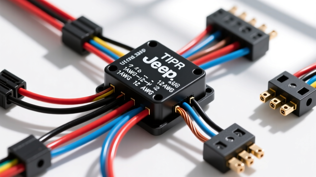
Demystifying the Fuse Relay Box for Beginners
For anyone stepping into the world of automotive lighting modifications, the fuse relay box can look like an intimidating maze of plastic, copper, and cryptic symbols. In modern vehicles, this component is often referred to as a Power Distribution Center (PDC) or, in the case of the highly popular 2007-2018 Jeep Wrangler JK, the Totally Integrated Power Module (TIPM). Understanding how to read a fuse relay box wiring diagram is the single most important fundamental skill you can develop before splicing a single wire. This guide breaks down the core concepts of tracing lighting circuits, decoding ISO relay pinouts, and selecting the correct AWG wire gauges for your auxiliary light bars and fog lights.
Core Symbols in Automotive Wiring Diagrams
Before tracing a circuit, you must understand the visual language of automotive schematics. Wiring diagrams do not show the physical layout of the wires; instead, they show the logical flow of electricity. According to the Haynes Automotive Electrical Manual, mastering these basic symbols is your first step:
- Straight Lines: Represent wires. A solid dot where lines intersect indicates a physical splice or junction. Crossing lines without a dot mean the wires do not connect.
- Zigzag Lines: Represent resistors or the internal electromagnetic coil inside a relay.
- Rectangles with Diagonal Lines: Represent switches (open or closed).
- Triangles or Rectangles with a Line Through Them: Represent diodes, which allow current to flow in only one direction (crucial for preventing flyback voltage in OEM TIPM relays).
- Ground Symbols: A vertical line with three descending horizontal lines, indicating a chassis or engine block ground point.
The ISO Mini Relay: The Heart of Lighting Mods
When you install an LED light bar or upgrade your halogen headlights, you are almost always adding an ISO Mini Relay to your circuit. The ISO 7588-1 Road Vehicles Relays standard dictates a universal 5-pin (or 4-pin) configuration. A wiring diagram will always label these pins with specific DIN numbers. Understanding these numbers is non-negotiable for proper installation.
| Pin Number | Circuit Type | Function in Lighting Diagram | Typical Wire Gauge |
|---|---|---|---|
| 30 | Load (Power In) | Constant 12V+ from the battery via a main fuse. | 12 AWG or 10 AWG |
| 87 | Load (Power Out) | Switched 12V+ output to the light bar or fog lights. | 14 AWG or 16 AWG |
| 86 | Control (Coil Power) | 12V+ trigger signal from the OEM switch or TIPM output. | 18 AWG |
| 85 | Control (Coil Ground) | Ground path to complete the electromagnetic coil circuit. | 18 AWG |
| 87a | Load (Normally Closed) | Outputs power when relay is OFF. Rarely used in lighting. | N/A |
Expert Note: Some OEM TIPM diagrams show a diode symbol bridging pins 85 and 86. This is a suppression diode designed to absorb the voltage spike when the relay coil is de-energized. If you are using an aftermarket relay harness with an internal diode, you must ensure pin 86 receives the positive trigger and pin 85 goes to ground; reversing them will short the circuit and blow your control fuse.
Step-by-Step: Tracing an Auxiliary Fog Light Circuit
Let us apply this knowledge to a real-world scenario: reading a diagram to wire aftermarket fog lights on a Jeep JK. Because the JK's TIPM manages high-current switching internally and limits auxiliary draws, the diagram will show us how to use the OEM fog light circuit merely as a trigger for an external relay.
- Locate the Trigger Source: The diagram shows the OEM fog light relay output exiting the TIPM at Connector C3, Pin 24. This wire is typically a 20 AWG Violet/White tracer wire. Instead of using a destructive 'vampire' T-tap, a proper diagram reading dictates using a Metri-Pack 280 female terminal to interface directly with the C3 connector block.
- Route the Control Circuit: Run an 18 AWG wire from this trigger source to Pin 86 on your external ISO relay. Connect Pin 85 to a clean, unpainted chassis ground using a ring terminal and a star washer to bite through the paint.
- Wire the Load Circuit: Run a 10 AWG wire from the positive battery terminal to an inline ATO fuse holder. According to SAE J1284 standards for blade fuses, the fuse must be rated for 125% of the continuous load. If your LED fog lights draw 12 Amps total, use a 15A or 20A ATO fuse. Route this fused 10 AWG wire to Pin 30 on the relay.
- Connect the Lights: Run 14 AWG wire from Pin 87 to the positive terminals of your fog lights. Ground the lights directly to the chassis using 14 AWG wire.
Wire Gauge and Fuse Sizing Reference Chart
Beginners often make the mistake of using wire that is too thin, leading to severe voltage drop, dim lights, and melted insulation. Always consult your wiring diagram for amperage ratings and cross-reference with this AWG chart based on standard 12V-14V automotive systems.
| Wire Gauge (AWG) | Max Ampacity (Chassis Wiring) | Common Lighting Application | Recommended Max Fuse |
|---|---|---|---|
| 10 AWG | 30 Amps | Main battery feed to relay block, 40-inch light bars | 30A |
| 12 AWG | 20 Amps | Relay to high-draw LED pods (e.g., dual 10W pods) | 20A |
| 14 AWG | 15 Amps | Standard LED fog lights, interior dome light upgrades | 15A |
| 16 AWG | 10 Amps | Low-draw accent lighting, license plate LEDs | 10A |
| 18 AWG | 5 Amps | Relay coil trigger wires (Pins 85 and 86) | 5A |
Real-World Troubleshooting with a Digital Multimeter
When your newly installed lighting system fails to turn on, the wiring diagram becomes your troubleshooting map. Never guess; test. Set your Digital Multimeter (DMM) to DC Volts and perform a voltage drop test.
A voltage drop test measures the difference in electrical potential between two points in a live circuit. A healthy connection should show less than 0.1V drop. If you place your red probe on the battery positive terminal and your black probe on Pin 30 of the relay while the circuit is active, and the meter reads 2.5V, you have a severe restriction (likely a corroded fuse holder or undersized wire) choking the current before it even reaches the relay. Move the black probe to Pin 87. If the voltage drop jumps by another 0.5V, your relay contacts are pitted or failing internally.
For the control side, check the voltage between Pin 86 and the battery negative terminal when the OEM switch is activated. If you read 12.4V but the relay does not click, move your black probe to Pin 85. If you now read 12.4V across the coil pins but still no click, your relay coil is open (broken internally). If you read 0V across the coil pins, your ground at Pin 85 is faulty.
Summary of Best Practices
Reading a fuse relay box wiring diagram is about understanding the relationship between the low-amperage control circuit and the high-amperage load circuit. Always use SAE-compliant fuses, adhere strictly to ISO relay pinouts, and respect AWG sizing limits. By treating the diagram as a logical flowchart rather than a physical map, you will eliminate guesswork, prevent electrical fires, and ensure your lighting modifications perform flawlessly for years to come.