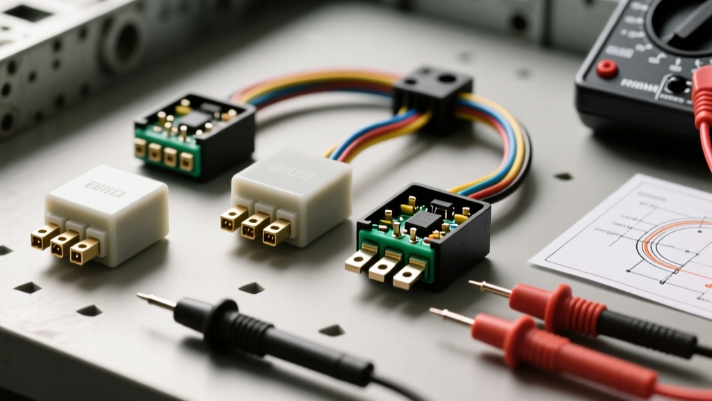
Understanding the Role of Relays in Automotive Lighting
When upgrading to high-draw LED light bars, installing auxiliary fog lights, or restoring aging headlight circuits, the ISO mini relay is the unsung hero of your wiring harness. Relays act as remote-controlled, heavy-duty electromagnetic switches. They allow a low-current trigger circuit (like a dashboard switch or a body control module) to safely control a high-current load (like 55W halogen bulbs or a 300W LED light bar) without melting the factory switch wiring.
However, relays are mechanical components subjected to extreme engine bay temperatures, moisture, and high electrical loads. Over time, internal contacts pit, coils burn out, and sockets melt. If your auxiliary lights are flickering, failing to turn on, or staying on after the ignition is off, you need to know exactly how to tell if a car relay is bad before you start tearing apart your wiring harness.
Symptoms of a Failing Lighting Relay
Before pulling out the multimeter, observe the behavior of your lighting circuit. A failing relay typically presents one of the following symptoms:
- Rapid Clicking Without Power: The coil is receiving enough voltage to pull the armature, but the contacts are too pitted to pass current to the lights.
- Intermittent Operation (Heat Soak):strong> The lights work when cold but fail after 15 minutes. This indicates a failing internal coil that expands and breaks continuity as it heats up.
- Melted Relay Socket: High resistance at the blade terminals generates excessive heat, melting the plastic ISO socket. This is common when running 14 AWG wire on a 40A relay without proper crimps.
- Lights Stuck 'On': The internal high-current contacts have welded together due to severe arcing, bypassing the switch entirely.
Standard ISO Mini Relay Pinout Configuration
To test a relay accurately, you must understand the DIN 72552 standard pin numbering system used on almost all automotive 4-pin and 5-pin ISO mini relays. The pin numbers are typically stamped into the plastic housing near the metal blades.
| Pin Number | Function | Typical Wire Color | Recommended AWG | Circuit Type |
|---|---|---|---|---|
| 30 | Common / Battery Feed (+12V) | Red or Black | 12 AWG or 14 AWG | High-Current Power |
| 85 | Coil Ground | Black | 16 AWG or 18 AWG | Low-Current Trigger |
| 86 | Coil Trigger (+12V Switch) | Blue or Switched Color | 16 AWG or 18 AWG | Low-Current Trigger |
| 87 | Normally Open (NO) Output | White or Yellow | 12 AWG or 14 AWG | High-Current Load |
| 87a | Normally Closed (NC) Output | N/A (Rare in lighting) | 14 AWG | High-Current Load |
Note: In standard lighting applications (headlights, fog lights, light bars), 4-pin relays are used. Pin 87a is only present on 5-pin changeover relays, which are more common in alarm systems or dual-function lighting setups.
Step-by-Step Guide: How to Tell if a Car Relay is Bad
To definitively diagnose the relay, remove it from the vehicle's fuse box or aftermarket harness. You will need a Digital Multimeter (DMM) and a 12V power source (a spare vehicle battery or a bench power supply).
Phase 1: Visual and Auditory Inspection
Inspect the relay blades for signs of corrosion, green copper oxide, or heat bluing. Look at the corresponding female Metri-Pack 2.8 terminals in the socket. If the plastic webbing between the socket cavities is melted or the female terminals are spread open (loss of tension), the socket must be replaced regardless of the relay's health. Spread terminals cause voltage drop and will destroy a new relay within weeks.
Phase 2: Testing the Electromagnetic Coil (Pins 85 & 86)
The coil is the low-current electromagnet that pulls the internal switch. According to Littelfuse Automotive Relay Guidelines, a standard 12V ISO relay coil should exhibit a specific resistance range.
- Set your multimeter to the Ohms (Ω) setting (usually the 200Ω range).
- Place one probe on Pin 85 and the other on Pin 86. Polarity does not matter for standard DC coils unless the relay has an internal flyback diode or resistor.
- Good Reading: 50 to 90 Ohms.
- Bad Reading (Open): 'OL' or Infinite. The internal copper wire is broken. The relay is dead.
- Bad Reading (Short): Near 0 Ohms. The coil windings have shorted together. This will blow your trigger circuit fuse immediately.
Phase 3: Testing the High-Current Switch Contacts (Pins 30, 87, 87a)
This phase tests the actual switch that sends power to your lights. Carbon buildup from arcing can cause severe voltage drop here.
- Set your multimeter to the Continuity or low-Ohms setting.
- Test 4-Pin (Normally Open): Place probes on Pin 30 and Pin 87. With no power applied, the meter should read 'OL' (Open Loop). If it reads continuity, the contacts are welded together (Bad).
- Test 5-Pin (Normally Closed): Place probes on Pin 30 and Pin 87a. With no power applied, the meter should read continuity (less than 0.5 Ohms). If it reads 'OL', the NC contacts are burnt (Bad).
- The 'Click' Test (Energizing the Coil): Using jumper wires, apply +12V to Pin 86 and Ground to Pin 85. You should hear a distinct, sharp mechanical 'click'. If you hear a dull buzz, the armature is sticking or the coil is weak.
- Loaded Contact Test: While the relay is energized (clicked 'on'), probe Pin 30 and Pin 87. The resistance should drop to less than 0.2 Ohms. If it reads 1.0 Ohm or higher, the contacts are pitted with carbon. Under a 20A lighting load, a 1.0 Ohm contact resistance will generate 400 Watts of heat (I²R), melting the relay from the inside out.
Common Failure Modes in Aftermarket Lighting Harnesses
When installing aftermarket LED light bars or off-road fog lights, relay failures are often caused by improper harness construction rather than a defective relay out of the box.
- Missing Flyback Diodes: When the electromagnetic coil de-energizes, it creates a high-voltage reverse spike (inductive kickback). Over time, this spike arcs across the internal contacts, pitting them. High-quality relays from manufacturers like Bosch or TE Connectivity often include an internal suppression resistor or diode to mitigate this.
- Undersized Trigger Wiring: Using 20 AWG wire for the trigger circuit over long runs (like routing to the rear of a truck bed) causes voltage drop. If the voltage reaching Pin 86 drops below 9V, the coil may not generate enough magnetic force to fully seat the high-current contacts, leading to arcing and failure.
- Moisture Ingress: Standard black ISO mini relays are not waterproof. If mounted in a wheel well or on a chassis rail, moisture wicks into the relay casing via capillary action through the wire crimps. Always use sealed, weather-resistant relays (often blue or grey with an epoxy fill) for exterior mounting.
Best Practices for Relay Replacement and Wiring
If you have determined the relay is bad, proper replacement procedures are critical to ensure the new component survives. According to industry wiring standards referenced by Waytek Wire, the connection at the socket is the most common point of failure.
- Use Proper Terminals: Never use generic spade connectors on an ISO mini relay. Use OEM-style Metri-Pack 2.8 or Weather-Pack female terminals with the correct open-barrel crimp dies. The crimp should secure both the wire conductor and the insulation grip.
- Apply Dielectric Grease: Apply a small dab of silicone dielectric grease to the male relay blades before inserting them into the socket. This prevents galvanic corrosion and moisture ingress without interfering with the electrical connection.
- Upgrade the Fuse: Ensure the inline fuse on Pin 30 is sized correctly for the wire gauge and the load. A 40A relay wired with 14 AWG TXL wire should be protected by a 20A or 25A MAXI or ATC fuse, placed as close to the battery positive terminal as possible.
- Solder vs. Crimp: Do not solder the wires directly to the relay blades. Solder creates a rigid stress point that will crack under engine vibration, leading to an open circuit. Always use a high-quality, sealed relay socket harness.
By systematically testing the coil resistance and switch continuity, you can confidently isolate the fault in your lighting system. Understanding how to tell if a car relay is bad saves hours of diagnostic guesswork and ensures your auxiliary lighting operates safely and reliably for years to come.