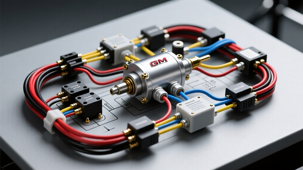
Decoding Car Electrical Wiring Problems: A Schematic-First Approach
When technicians and DIY enthusiasts encounter complex car electrical wiring problems, the most common mistake is resorting to "parts darts"—replacing relays, modules, or sensors without consulting the schematic. A wiring diagram is not merely a visual map of connections; it is a logical sequence of voltage supplies, ground paths, serial data networks, and load controls. To effectively diagnose modern automotive electrical faults, you must learn to read the diagram from the power source, through the control module, and down to the actuator.
In this complete walkthrough, we will dissect a notorious circuit prone to failure: the Pulse Width Modulated (PWM) Fuel Pump Control Module (FPCM) found on 2007-2013 GM Silverado and Sierra 1500 trucks (5.3L/6.2L V8). By tracing this specific schematic, you will learn how to isolate power, verify data lines, and test high-current grounds to solve intermittent stalling, crank-no-start, and SES (Service Engine Soon) light issues.
Case Study: The GM FPCM Circuit Architecture
Unlike older vehicles that use a simple 12V relay to run the fuel pump at full speed, modern GM trucks utilize an FPCM to vary fuel pressure based on engine demand. The FPCM receives a request via the GMLAN serial data bus from the Engine Control Module (ECM) and outputs a PWM signal to the fuel pump flow control module. This complexity introduces multiple failure points where car electrical wiring problems frequently manifest, particularly in the high-current ground circuits and the twisted-pair data lines.
FPCM Connector C1 Pinout & Wire Specifications
Before touching a multimeter, you must identify the correct cavities. The FPCM utilizes a 16-cavity black connector (Connector C1). Below is the critical pinout reference for diagnosis:
| Pin | Circuit ID | Wire Color | AWG | Function |
|---|---|---|---|---|
| A | 1339 | Red | 12 | Battery Feed (FPCM 20A Fuse) |
| B | 150 | Black | 12 | Chassis Ground (G402) |
| H | 5987 | Light Blue | 18 | GMLAN Serial Data (+ / High) |
| I | 5988 | Light Blue/Black | 18 | GMLAN Serial Data (- / Low) |
| L | 8920 | Grey | 14 | Fuel Pump PWM Control Signal |
| M | 8921 | Black/White | 14 | Fuel Pump Low Reference |
Step-by-Step Diagram Walkthrough & Verification
1. Tracing the Battery Feed (Circuit 1339)
According to the schematic, Pin A receives constant battery voltage from the underhood fuse block. While a test light might illuminate, it only proves the presence of voltage, not the capacity to carry current. To properly diagnose voltage drop on this 12 AWG red wire:
- Set your Digital Multimeter (DMM) to DC Volts.
- Place the red probe on the positive battery terminal and the black probe on FPCM Connector C1, Pin A (back-probe the connector while connected).
- Turn the ignition to the "Run" position to wake the module.
- A healthy circuit will show less than 0.10V drop. If you read 0.50V or higher, you have high resistance—likely corrosion at the fuse block spade or a failing crimp terminal.
2. Verifying the Chassis Ground (Circuit 150 & G402)
Ground G402 is located on the left frame rail, near the fuel tank. This is a primary culprit for many car electrical wiring problems in GM trucks. The 12 AWG black wire must handle up to 15 amps when the fuel pump is under heavy load (e.g., wide-open throttle). A standard continuity test will mislead you; a single strand of 12 AWG copper will ring continuous on a DMM but will instantly fail under a 15A load.
The Voltage Drop Ground Test: Place your DMM's red probe on FPCM Pin B and your black probe directly on the negative battery terminal. Command the fuel pump on via a bi-directional scan tool. A voltage drop exceeding 0.20V indicates a compromised G402 ground. Remove the G402 bolt, clean the frame rail to bare metal with a wire brush, apply dielectric grease, and torque to factory specifications.
3. The GMLAN Serial Data Line (Circuits 5987 & 5988)
The ECM commands the FPCM via a high-speed Controller Area Network (CAN) bus. If this twisted pair of 18 AWG wires is compromised, the ECM loses communication, triggering a U0100 or U0073 diagnostic trouble code (DTC) and disabling the fuel pump. As outlined in the AA1Car CAN Bus Diagnostic Guide, CAN bus faults are rarely module failures; they are almost always wiring issues.
- Termination Resistance Test: Disconnect the negative battery cable and unplug the FPCM. Set your DMM to Ohms. Measure across pins H and I. You should read approximately 60 ohms (the result of two 120-ohm termination resistors in parallel across the network). A reading of 120 ohms means one side of the network is open; a reading near 0 ohms indicates a short between the High and Low lines.
- Physical Inspection: Check the harness where it routes over the transmission bell housing. Chafing against the aluminum housing will pierce the 18 AWG insulation, causing a short-to-ground that crashes the entire GMLAN network.
4. PWM Output to the Fuel Pump (Circuit 8920)
Pin L outputs a Pulse Width Modulated signal to the pump. You cannot measure this accurately with standard DC Volts. Switch your DMM to Duty Cycle (%) or use an oscilloscope. At idle, the FPCM typically commands a 50% duty cycle (approx. 55 PSI). Under heavy acceleration, this ramps to 90% (approx. 85 PSI). If the duty cycle is present at the FPCM but missing at the fuel tank sender, the 14 AWG grey wire has an open circuit, often due to "green death" (capillary corrosion) inside the harness loom.
Diagnostic Decision Tree: Crank, No-Start (SES Light Illuminated)
Use this structured workflow to isolate the fault without replacing the FPCM or fuel pump prematurely.
- Symptom: Engine cranks but will not start. Scan tool shows U0100 (Lost Communication with FPCM).
- Step 1: Check Data Link. Measure resistance across C1 Pins H & I (Battery disconnected).
- If ~60 Ohms: Wiring to module is intact. Proceed to Step 2.
- If 120 Ohms or Open: Check for broken 18 AWG Light Blue wires between ECM and FPCM.
- Step 2: Check Module Power. Reconnect battery. Measure voltage at Pin A.
- If < 11.5V: Check FPCM 20A fuse and underhood fuse block for corrosion.
- If > 12.0V: Proceed to Step 3.
- Step 3: Check Module Ground. Perform voltage drop test on Pin B (Circuit 150) while cranking.
- If > 0.20V: Service ground G402 on the left frame rail.
- If < 0.10V: Power and Ground are verified. The FPCM module is likely internally faulted and requires replacement and programming.
Advanced Repair Standards & Avoiding Secondary Failures
When repairing the 12 AWG or 14 AWG wires in this circuit, never use "T-taps" or twist-on connectors. Piercing the insulation of modern SAE J1128 compliant primary automotive cable exposes the copper to moisture, leading to capillary action where water wicks under the insulation, destroying the wire feet away from the repair site.
Always use OEM-style solder-seal heat shrink connectors or ultrasonic splices. For the 18 AWG GMLAN data lines, any repair must maintain the twisted-pair geometry to prevent electromagnetic interference (EMI) from the ignition coils, which will corrupt the serial data packets and cause intermittent stalling. For foundational circuit theory and repair methodologies, refer to the AutoShop 101 Electrical Circuits Training Manual.
By systematically walking through the schematic—verifying the heavy-gauge power and ground paths before condemning the data lines or the module itself—you eliminate guesswork and permanently resolve even the most frustrating car electrical wiring problems.