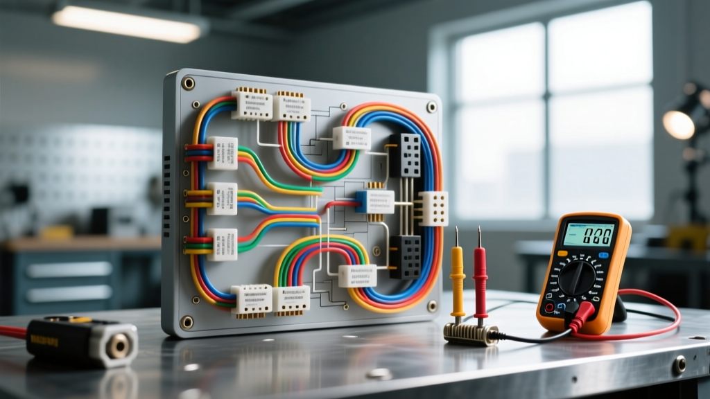
Introduction to Welltek Auto Electrical Diagnostics
Entering the world of automotive wiring can feel overwhelming, but mastering Welltek auto electrical diagnostics provides a structured, logical pathway to solving complex vehicle faults. Whether you are chasing a no-crank condition, a flickering dashboard, or a dead battery every morning, your digital multimeter (DMM) is your most vital tool. As a beginner, the goal is to move away from 'parts swapping' and toward systematic fault-finding. This guide breaks down the fundamental diagnostic tests you can perform with a Welltek DMM, focusing on real-world applications, specific wire gauges, and industry-standard connector pinouts.
Automotive electrical systems operate on a simple premise: a 12-volt DC source (the battery) pushes current through a conductor (wire) to perform work (load), and returns to the source via a ground path. When a circuit fails, it is almost always due to unwanted resistance in the power side, the ground side, or the load itself. By learning to measure voltage drop, current draw, and continuity, you can isolate any fault in a modern vehicle's harness.
Setting Up Your Welltek DMM for Automotive Use
Before probing any connector, you must configure your meter correctly to avoid blowing internal fuses or damaging sensitive Powertrain Control Modules (PCMs). Modern vehicles utilize CAN-bus networks operating at low voltages and high frequencies; improper meter settings can introduce resistance or short circuits into these data lines.
- Voltage (DC): Set your Welltek DMM to the 20V DC range (or auto-ranging) for 95% of automotive power and signal testing.
- Resistance/Continuity: Used strictly on dead circuits. Never measure resistance on a live wire; the voltage will feed back into the meter and destroy the internal protection.
- Current (Amps): Requires moving the red probe to the dedicated 10A or mA port. This places the meter in series with the circuit. Failing to move the probe back to the V/Ω port after testing is the #1 cause of blown DMM fuses.
Fundamental Test 1: Voltage Drop Testing (The Golden Rule)
Voltage drop testing is the cornerstone of Welltek auto electrical diagnostics. Unlike a simple continuity test, voltage drop testing is performed while the circuit is under load (active). It measures the exact amount of voltage 'lost' as current pushes through a connection or wire. According to the Fluke Voltage Drop Testing Guide, unwanted resistance generates heat and robs the load of the power it needs to function.
How to Perform a Starter Circuit Voltage Drop Test
If a vehicle cranks slowly, beginners often replace the battery or starter. An expert performs a voltage drop test on the 4 AWG battery cables first.
- Set the Welltek DMM to DC Volts.
- Connect the red probe to the battery positive post (not the clamp, the actual lead post).
- Connect the black probe to the starter motor B+ terminal stud.
- Disable the ignition or fuel system and crank the engine for 5 seconds.
- Read the display. A reading of 0.15V means the cable and connections are excellent. A reading of 2.4V indicates severe corrosion, likely under the battery terminal lug or at the starter solenoid.
Acceptable Voltage Drop Limits
| Circuit Component | Wire Gauge (AWG) | Maximum Allowable Drop | Common Failure Mode |
|---|---|---|---|
| Heavy Battery Cables | 4 AWG to 1/0 AWG | 0.50V (500mV) | Corroded lug crimps, loose chassis bolts |
| Standard Power Wires | 10 AWG to 14 AWG | 0.20V (200mV) | Green copper oxide inside insulation |
| Connectors & Terminals | Metri-Pack 280 / Weather-Pack | 0.10V (100mV) per pin | Terminal fretting, spread female pins |
| Switches & Relays | Internal Contacts | 0.30V (300mV) | Carbon tracking, pitted contact surfaces |
| Ground Paths (Chassis) | 18 AWG to 8 AWG | 0.10V (100mV) | Paint/sealant blocking bare metal contact |
Fundamental Test 2: Parasitic Draw Diagnosis
A parasitic draw occurs when a module or short circuit continues to pull current from the battery after the ignition is turned off. While older vehicles tolerated up to 50mA (0.05A), modern vehicles with advanced telematics and CAN networks should ideally sit below 30mA once fully asleep.
The CAN-Bus Sleep Mode Trap
The most common beginner mistake in Welltek auto electrical diagnostics is measuring parasitic draw immediately after turning off the car. Modern modules (BCM, TCM, Infotainment) take anywhere from 20 to 45 minutes to enter 'sleep mode'. If you connect your DMM and read 1.8 Amps, you are likely just seeing the network awake, not a fault.
Step-by-Step Parasitic Draw Procedure
- Prep the Vehicle: Close all doors, hood, and trunk. Latch the hood release physically so the under-hood fuse box is accessible without triggering the 'hood open' switch.
- Setup the DMM: Move the Welltek red probe to the 10A port. Set the dial to 10A DC.
- Break the Circuit: Disconnect the negative battery terminal. Connect the DMM in series: red probe to the disconnected negative cable, black probe to the negative battery post.
- Wait for Sleep: Wait 30-45 minutes. You will see the current drop from ~2.0A down to ~0.8A, then ~0.3A, and finally settle below 0.05A (50mA) as modules power down sequentially.
- Isolate the Fault: If the draw remains high (e.g., 0.45A), begin pulling fuses one by one. When the draw drops to 0.02A, the circuit you just disabled contains the fault.
Expert Tip: Never use the mA port on your DMM to initially check parasitic draw. If the vehicle is awake and pulls 2 Amps, you will instantly blow the meter's internal 400mA fuse. Always start on the 10A port, and only switch to the mA port for precise readings once the vehicle is confirmed asleep.
Fundamental Test 3: Sensor Signal & Continuity Checks
When diagnosing driveability issues, you must verify the wiring harness between the PCM and the sensor. Let's use a standard 3-wire Manifold Absolute Pressure (MAP) sensor housed in a GM-style Metri-Pack 280 connector as an example.
MAP Sensor Pinout & Diagnostics
- Pin A (Ground): Black wire, 18 AWG. Low-reference ground to PCM.
- Pin B (Signal): Dark Green wire, 20 AWG. 0-5V analog signal.
- Pin C (5V Reference): Red/White tracer wire, 20 AWG. 5-Volt supply from PCM.
To test the harness integrity without back-probing and damaging the weather seals, use a breakout box or a dedicated pigtail adapter. With the key ON, engine OFF (KOEO):
- Measure Pin C to Battery Negative. You should read exactly 4.9V to 5.1V. If it reads 0V, check the AutoShop 101 wiring diagrams for an open circuit or a short to ground pulling the PCM's 5V reference bus down.
- Measure Pin A to Battery Negative. You should read less than 0.05V (50mV). If it reads 2.5V, the PCM ground path is compromised, often due to corrosion at the main engine block ground stud (typically a 15mm bolt torqued to 35 lb-ft).
- Check Continuity: Turn the key OFF. Switch the Welltek DMM to the Ohms (Ω) setting. Probe Pin B at the sensor connector and the corresponding pin at the PCM connector. A good 20 AWG wire spanning 4 feet should read less than 1.5 Ohms. If it reads OL (Open Loop), the wire is broken inside the insulation, a common issue near engine hinges and sharp bends.
Wire Gauge and Fuse Protection Standards
When repairing a harness, you must adhere to SAE J1128 Primary Cable Standards regarding current capacity. Fuses are designed to protect the wire, not the component. If you replace a blown 15A fuse with a 20A fuse, you risk melting the 16 AWG harness wire before the fuse blows, potentially causing an electrical fire.
| Wire Gauge (AWG) | Strand Count (Standard) | Max Continuous Amperage | Required Max Fuse Size |
|---|---|---|---|
| 18 AWG | 16 Strands | 10 Amps | 10A (Mini/ATO) |
| 16 AWG | 26 Strands | 15 Amps | 15A (Mini/ATO) |
| 14 AWG | 41 Strands | 20 Amps | 20A (ATO) |
| 12 AWG | 65 Strands | 25 Amps | 25A (ATO) |
| 10 AWG | 104 Strands | 35 Amps | 30A (Maxi/ATO) |
Common Beginner Mistakes to Avoid
Even with the best Welltek auto electrical diagnostics equipment, poor technique will yield false data. Avoid these critical errors:
- Piercing Wire Insulation: Never use a 'T-pin' or ice pick to pierce a wire to check for voltage. This introduces moisture directly to the copper strands, guaranteeing green corrosion and a broken wire within 6 months. Always back-probe connectors using specialized, ultra-thin terminal probes.
- Ignoring Ground Quality: A sensor reading erratic voltage is rarely a bad sensor; 80% of the time, it is a poor shared ground. Always verify the ground circuit's voltage drop before condemning a $150 OEM sensor.
- Using Test Lights on SRS/Airbag Circuits: Never use a standard incandescent test light or apply 12V directly to an airbag squib circuit. The current draw from the test light's filament is enough to deploy the airbag, causing severe injury. Use only high-impedance DMMs or dedicated SRS simulators.
By mastering these foundational tests—voltage drop under load, systematic parasitic draw isolation, and precise harness continuity checks—you transition from a parts replacer to a true automotive electrical diagnostician. Keep your Welltek DMM calibrated, respect the AWG limits, and always let the voltage data guide your wrenches.