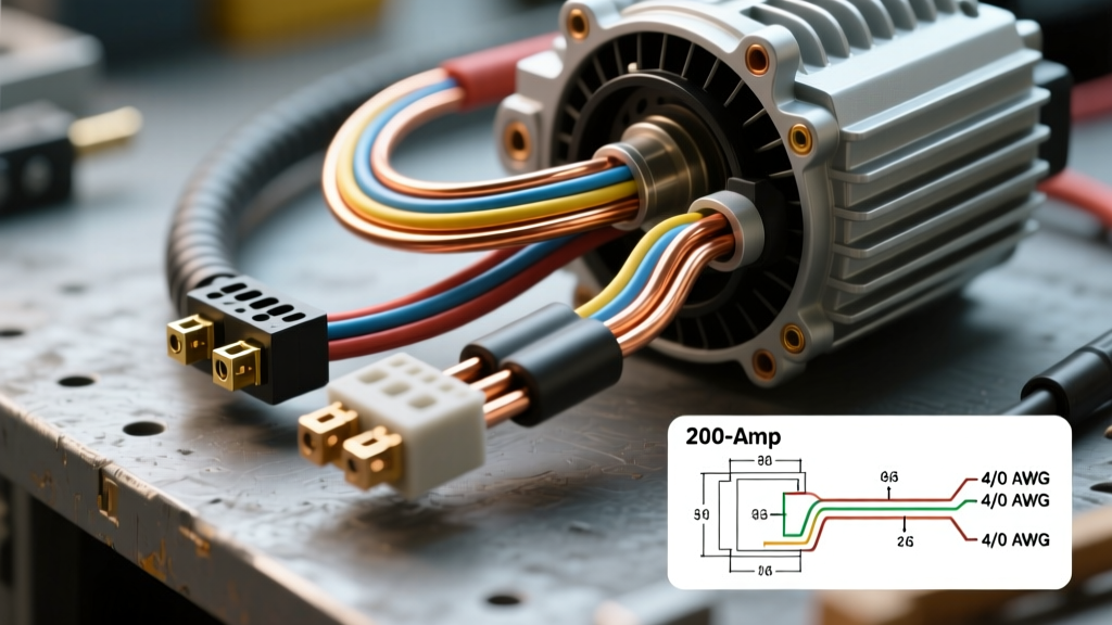
Translating '200 Amp Service' to Automotive High-Output Systems
In residential electrical work, '200 amp service' refers to the main breaker panel capacity. However, in the automotive and overland engineering sectors, selecting the correct wire gauge for 200 amp service refers to building a high-output charging architecture capable of sustaining 200A to 250A of continuous DC current. This is typically required when upgrading heavy-duty trucks, RVs, or expedition vehicles with high-output alternators (such as 6-phase Denso or Remy units) to support massive inverter loads, winches, and LiFePO4 auxiliary battery banks.
Unlike AC residential wiring governed by the NEC, automotive DC wiring is governed by SAE J1128 standards and strict voltage drop limitations. A 200A DC load will instantly melt undersized copper and cause severe alternator diode failure due to heat soak. This complete wiring diagram walkthrough breaks down the exact AWG requirements, node-by-node routing, and termination specifications required to safely engineer a 200A automotive electrical service.
Schematic Walkthrough: The 200A High-Output Architecture
To understand the wire gauge requirements, we must trace the schematic from the alternator stator to the battery bank. Below is a node-by-node walkthrough of a properly engineered 200A charging circuit.
Node A: Alternator B+ Output Terminal
The journey begins at the alternator's B+ (Battery Positive) stud. High-output 200A+ alternators generate immense heat. The factory wiring harness is entirely inadequate. You must route a dedicated, heavy-gauge cable directly from the B+ stud. Most high-output alternators utilize an M8 or M10 threaded stud. The wire must be terminated with a tinned copper, 3/8-inch or M10 closed-end ring terminal, torqued precisely to the manufacturer's specification (typically 10-12 Nm) to prevent micro-arcing and subsequent stud failure.
Node B: Primary Circuit Protection (The Fuse)
Within 18 inches of the B+ terminal, the main power cable must pass through a primary fuse. For a 200A continuous service, a 250A fuse is standard. However, the type of fuse is critical. Standard ANL fuses are common, but if your system includes a high-capacity lithium (LiFePO4) battery bank, you must use a Class T fuse. Class T fuses offer an Ampere Interrupting Capacity (AIC) of 20,000 amps, which is necessary to safely extinguish the massive DC arc a lithium bank can produce during a dead short.
Node C: The Common Busbar
From the fuse, the cable routes to a centralized, tinned copper power busbar mounted in a dry, ventilated area of the engine bay or cab. This busbar acts as the distribution point for the starter motor, the main chassis battery, and the rear auxiliary battery bank. Using a single 2/0 AWG feed to a busbar, rather than stacking multiple ring terminals on the alternator B+ stud, prevents mechanical stress and thermal bottlenecks at the alternator.
Node D: Auxiliary Battery Bank & BMS Integration
The final leg runs from the busbar to the auxiliary battery bank. If utilizing a Battery Management System (BMS) for lithium cells, the BMS charge-limiting parameters must be programmed to cap the input at the battery's maximum continuous charge rating (often 100A-200A), ensuring the 200A service wire is never overwhelmed by a deeply depleted bank demanding maximum current.
Wire Gauge Selection & Voltage Drop Mathematics
Selecting the wire gauge for 200 amp service is not just about preventing the wire from catching fire; it is about preventing voltage drop. Automotive alternators require a precise voltage reference at the battery to regulate output. If voltage drop occurs across the wire, the alternator's internal regulator will overcompensate, pushing 15.5V+ at the B+ terminal to achieve 14.4V at the battery. This over-voltage will boil lead-acid batteries and trigger high-voltage disconnects on lithium BMS units.
According to Blue Sea Systems circuit calculation guidelines, charging circuits should experience a voltage drop of no more than 1% (approx. 0.14V on a 14.4V system). Below is the specification chart for SAE J1128 Type SGT battery cable at a 200A continuous draw.
| AWG Size | Strand Count (30 AWG) | Max Ampacity (Engine Bay) | Resistance per 10ft (mΩ) | Voltage Drop @ 200A (per 10ft run) | Verdict for 200A Service |
|---|---|---|---|---|---|
| 4 AWG | 1,045 | 120A | 2.48 mΩ | 0.496V (3.4%) | FAIL: Fire Hazard & Severe Drop |
| 2 AWG | 1,665 | 160A | 1.56 mΩ | 0.312V (2.1%) | FAIL: Exceeds 1% Drop Limit |
| 1/0 AWG (0) | 2,100 | 210A | 0.98 mΩ | 0.196V (1.3%) | MARGINAL: Acceptable for very short runs (<5ft) |
| 2/0 AWG (00) | 4,180 | 260A | 0.78 mΩ | 0.156V (1.08%) | OPTIMAL: Recommended for runs up to 15ft |
| 3/0 AWG (000) | 5,250 | 310A | 0.62 mΩ | 0.124V (0.86%) | OVERKILL: Required for rear-mounted batteries (>20ft) |
Expert Recommendation: For a standard heavy-duty truck upgrade where the alternator is in the front and the auxiliary batteries are in the rear bed or trunk (a total round-trip wire length of 30+ feet), 2/0 AWG is the absolute minimum wire gauge for 200 amp service. If the run exceeds 20 feet one-way, you must step up to 3/0 AWG or 4/0 AWG to maintain the 1% voltage drop threshold.
Wire Type: Why SAE J1128 Type SGT is Mandatory
Never use residential THHN wire or cheap CCA (Copper Clad Aluminum) wire for automotive 200A service. The engine bay is a hostile environment characterized by extreme heat cycles, hydrocarbon exposure, and high-frequency vibration.
- Strand Flexibility: Type SGT (Standard General Use) battery cable utilizes thousands of fine 30 AWG copper strands. This allows the cable to absorb engine movement and chassis flex without suffering from work-hardening and internal copper fracturing, which is a common failure mode in solid-core or coarse-strand wires.
- Insulation Chemistry: SGT insulation is formulated to resist battery acid, engine oil, and transmission fluid. It also features a higher temperature rating (105°C continuous) compared to standard GXL or TXL wires.
- Material Purity: Ensure the wire is 99.9% pure electrolytic tough pitch (ETP) copper. CCA wire has a significantly higher resistance and will overheat at 200A DC, even if the AWG gauge appears correct on the outside.
Termination and Crimping Specifications
The most common failure point in a 200A charging system is not the wire itself, but the termination. A poor crimp introduces milliohms of resistance, which at 200A translates to massive localized heat generation ($P = I^2R$).
The Hex-Crimp Standard
For 1/0 AWG and 2/0 AWG cables, standard indent crimpers are insufficient. You must use a hex-crimp or indented-nest hydraulic crimper with the correct die size. A hex crimp compresses the copper strands and the terminal barrel into a solid, hexagonal mass, eliminating air pockets where moisture could accumulate and cause galvanic corrosion.
Adhesive-Lined Heat Shrink
After crimping, the termination must be sealed with dual-wall, adhesive-lined heat shrink tubing (minimum 3:1 shrink ratio). When heated, the inner thermoplastic adhesive melts and flows into the wire strands, creating a waterproof seal that prevents capillary action from wicking moisture under the insulation—a phenomenon that leads to green copper oxide buildup and eventual high-resistance failure.
Real-World Troubleshooting & Failure Modes
Even with the correct wire gauge for 200 amp service, high-output systems can exhibit specific failure modes. Use this diagnostic tree if your system is underperforming:
- Symptom: Alternator whining and battery overcharging (15V+).
Cause: High resistance in the main B+ cable or a corroded busbar connection causing severe voltage drop. The alternator's internal regulator senses low voltage at the battery and maxes out the stator output.
Fix: Perform a loaded voltage drop test. Place your multimeter probes on the alternator B+ stud and the battery positive terminal while the system is under a 150A load. Any reading above 0.15V indicates a bad crimp or undersized wire. - Symptom: Melted fuse block or discolored ring terminals.
Cause: Improper crimping technique (using an undersized die) or failure to use tinned copper terminals. Bare copper oxidizes rapidly in engine bays, increasing resistance over time.
Fix: Cut back the wire to fresh copper, re-terminate with marine-grade tinned terminals, and verify torque specs with a calibrated inch-pound torque wrench. - Symptom: Alternator diode bridge failure.
Cause: Disconnecting the battery while the engine is running (load dump), or running the 200A wire too close to exhaust headers without high-temperature fiberglass sleeving, causing a short to ground that bypasses the main fuse.
Fix: Route all 2/0 AWG main power cables away from exhaust manifolds. Use split-loom and high-temp silicone sleeving where clearance is under 6 inches.
Final Engineering Considerations
Upgrading to a 200A automotive service is a major modification that bridges the gap between standard vehicle electrical systems and heavy-duty marine/RV architectures. By adhering to MAD Electrical's heavy-duty wiring principles, utilizing 2/0 AWG SAE J1128 Type SGT pure copper cable, and employing hex-crimp terminations with Class T circuit protection, you ensure that your high-output alternator can safely and efficiently deliver maximum current without the risk of thermal runaway or voltage starvation. Always verify your specific alternator's maximum continuous output rating, as many '250A' alternators can only sustain 200A before thermal rollback engages.