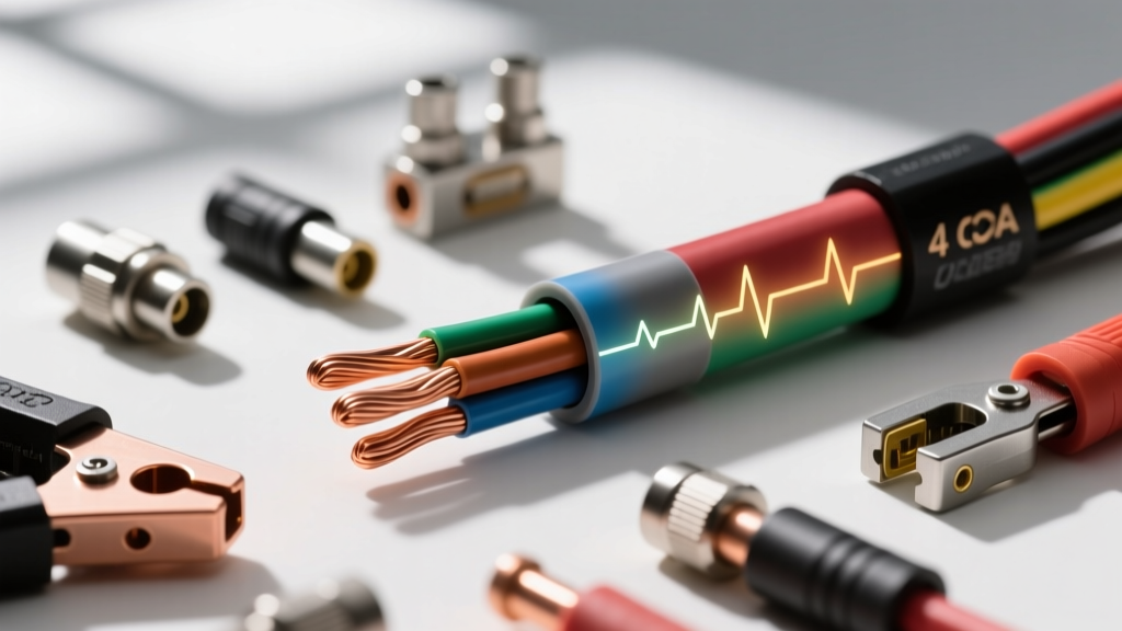
The Physics of 4 AWG: OFC vs. CCA Conductors
When building high-output mobile audio systems, the transition to 4 gauge power wire for amp configurations marks the threshold between standard aftermarket upgrades and serious competition-level electrical demands. A true 4 AWG conductor possesses a cross-sectional area of 21,150 circular mils (approx. 107.2 mm²). However, the car audio market is flooded with undersized, misleadingly labeled cables. To engineer a reliable power delivery network, you must first understand the metallurgical differences between Oxygen-Free Copper (OFC) and Copper-Clad Aluminum (CCA).
Conductivity and Thermal Runaway
OFC wire is drawn from 99.9% pure copper, offering a baseline DC resistance of approximately 0.2485 ohms per 1,000 feet at 20°C. CCA wire, conversely, features an aluminum core with a thin copper electroplating. Because aluminum has only 61% of the conductivity of copper, a 4 AWG CCA wire exhibits roughly 1.6 times the DC resistance of its OFC counterpart (approx. 0.397 ohms per 1,000 feet).
In high-current scenarios, this resistance differential manifests as heat. According to Joule's First Law ($P = I^2R$), the power dissipated as heat in a CCA cable will be 60% higher than in an OFC cable of the exact same gauge and length. Over time, this thermal cycling degrades the PVC insulation jacket, leading to micro-fractures, short circuits, and in extreme cases, engine bay fires.
Calculating True DC Current Draw
Amplifier RMS wattage ratings do not directly equate to alternator load. To properly spec your 4 gauge power wire for amp runs, you must calculate the actual DC current draw based on the amplifier's topology and efficiency class. The governing formula is:
$I = \frac{P_{RMS}}{V \times \eta}$
- $I$ = Current Draw (Amperes)
- $P_{RMS}$ = Total RMS Wattage Output
- $V$ = System Voltage (Use 12.5V for a realistic alternator-under-load baseline, not 14.4V)
- $\eta$ = Amplifier Efficiency
Topology Efficiency Variables
Modern Class D monoblock subwoofer amplifiers operate at roughly 80% efficiency ($\eta = 0.80$). A 1,200W RMS Class D amplifier will draw: $1200 / (12.5 \times 0.80) = \mathbf{120 Amps}$.
Conversely, Class A/B amplifiers used for full-range SQ (Sound Quality) builds operate at roughly 60% efficiency ($\eta = 0.60$). A 1,200W RMS Class A/B amplifier will draw: $1200 / (12.5 \times 0.60) = \mathbf{160 Amps}$.
While 4 AWG OFC wire is rated for up to 150A in chassis wiring applications (per the AWG Wire Copper Gauge Chart), a 160A continuous load on a Class A/B system requires either upgrading to 2 AWG or ensuring the 4 AWG run is kept exceptionally short to mitigate thermal saturation.
Voltage Drop Analysis & Maximum Run Lengths
Voltage drop is the silent killer of audio fidelity. When an amplifier's B+ terminal receives less than 11.5V during heavy bass transients, the internal power supply rails collapse, triggering protection circuits or generating severe square-wave clipping. Below is a technical voltage drop matrix comparing OFC and CCA 4 AWG wire across standard vehicle run lengths (Positive + Ground return path calculated).
| Total Circuit Length (ft) | Current Draw (A) | OFC Voltage Drop (V) | CCA Voltage Drop (V) | System Status |
|---|---|---|---|---|
| 15 ft (Sedan/Coupe) | 120A | 0.89V | 1.43V | OFC Optimal / CCA Marginal |
| 20 ft (SUV/Truck) | 120A | 1.19V | 1.90V | OFC Acceptable / CCA Failing |
| 15 ft (Sedan/Coupe) | 150A | 1.11V | 1.78V | OFC Marginal / CCA Critical |
| 20 ft (SUV/Truck) | 150A | 1.49V | 2.38V | OFC Failing / CCA Dangerous |
Note: A voltage drop exceeding 1.0V on the main power delivery network indicates the need for a larger gauge wire or the addition of a secondary alternator and lithium battery bank.
Insulation Standards & Engine Bay Routing
The copper inside the jacket is only half the equation. Automotive environments expose wiring to extreme thermal cycling, vibration, and corrosive chemicals. Standard consumer wire utilizes basic PVC (Polyvinyl Chloride) which becomes brittle at -20°C and begins to soften and melt around 80°C.
For professional installations, ensure your 4 gauge power wire meets the SAE J1128 Low Tension Primary Cable Standard or the more stringent SAE J2582 standard for high-temperature applications. You must look for XLPE (Cross-Linked Polyethylene) insulation. XLPE is chemically altered to form a 3D molecular bond, raising the continuous temperature rating to 125°C and short-circuit ratings up to 200°C. This is non-negotiable when routing power cables through the firewall grommet near exhaust manifolds or turbocharger downpipes.
Termination Hardware & Crimping Dynamics
The most common point of failure in a 4 AWG power network is not the wire itself, but the termination. High-current DC connections require massive surface area contact and absolute mechanical stability.
The Dangers of Soldering High-Current Lugs
While soldering is excellent for low-current signal wires, it is highly discouraged for 4 AWG main power lugs. Solder (tin/lead or tin/copper alloys) has a significantly higher electrical resistance than copper. Under extreme continuous load, the solder joint can act as a heating element. Furthermore, solder wicks into the copper strands via capillary action, creating a rigid, brittle section of wire right at the crimp barrel. In a high-vibration automotive environment, this rigid point creates a fulcrum, leading to strand fatigue and eventual green rot (copper oxidation) inside the insulation.
Hex-Crimp vs. Hammer Crimp
Never use hammer-crimp tools for 4 AWG terminals. They deform the copper unevenly and fail to achieve the necessary cold-weld compression. You must use a dedicated hydraulic or heavy-duty ratcheting hex-crimp tool. A proper hex crimp compresses the 294 strands of 0.32mm wire uniformly, eliminating air pockets where moisture and oxygen could initiate corrosion.
Always seal the termination with dual-wall heat shrink. The inner wall contains a polyamide adhesive that melts and flows into the wire strands, creating a hermetic, waterproof seal that prevents capillary wicking of water from the trunk back to the battery terminal.
Fusing Protocols: ANL vs. Class T
Your 4 gauge power wire must be protected within 18 inches of the vehicle's main battery positive terminal. While 150A ANL fuses are standard in retail kits, they possess an AIC (Ampere Interrupt Capacity) of only 2,700 amps. If you are upgrading to modern high-density Lithium Iron Phosphate (LiFePO4) batteries, which can deliver catastrophic fault currents exceeding 10,000 amps during a dead short, an ANL fuse may physically arc and sustain a plasma fire before clearing the circuit.
For advanced builds utilizing lithium chemistry or multiple alternators, mandate the use of Class T fuses. Class T fuses feature an AIC rating of 20,000 amps and utilize a fast-acting graphite element that safely quenches high-energy DC arcs.
Distribution Block Torque Specifications
When terminating 4 AWG wire into a distribution block, the set screw torque is critical. Most mobile audio distribution blocks utilize M8 or M6 brass or copper set screws.
- M8 Set Screw: Torque to 4.5 - 5.0 Nm (approx. 40-44 in-lbs).
- M6 Set Screw: Torque to 2.5 - 3.0 Nm (approx. 22-26 in-lbs).
By respecting the metallurgical limits, calculating true DC loads, and adhering to strict SAE termination protocols, your 4 gauge power wire network will deliver flawless, unimpeded current to your amplifiers for the lifespan of the vehicle.