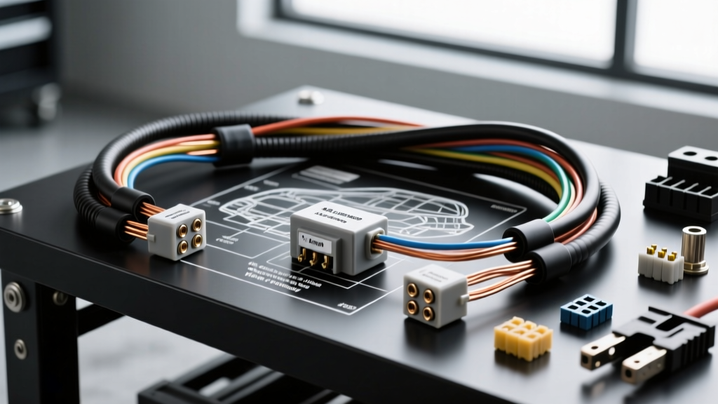
Introduction to 16-Amp Automotive Circuits
When building or repairing automotive electrical systems, a 16-amp continuous draw represents a critical threshold. This specific amperage is commonly seen in high-demand aftermarket accessories such as dual SPAL electric cooling fans on low speed, large inline fuel pumps, heavy-duty seat heaters, and auxiliary LED light bars. Unlike low-draw circuits that can be safely managed with 18 or 16 AWG wire, a 16-amp load requires careful consideration of wire gauge, insulation temperature ratings, and voltage drop. In this comprehensive guide, we will determine the exact wire gauge for 16 amps and walk through a complete, professional-grade relay wiring diagram to ensure your installation is safe, efficient, and reliable.
Calculating the Ideal Wire Gauge for 16 Amps
The most frequent question among automotive electricians is whether 14 AWG or 12 AWG wire is required for a 16-amp circuit. To answer this, we must look beyond basic household alternating current (AC) charts and refer to direct current (DC) automotive standards, specifically the SAE J1128 Standard for low-tension primary cable.
SAE J1128 vs. Standard AWG Charts
Standard American Wire Gauge (AWG) charts often rate 14 AWG copper wire at 15 to 20 amps. However, these charts typically assume a chassis wiring environment with ambient temperatures around 77°F (25°C). In an automotive engine bay, ambient temperatures frequently exceed 180°F (82°C) near the exhaust manifold and radiator. As temperature increases, the electrical resistance of copper increases, and the insulation's ability to dissipate heat decreases. SAE J1128 mandates strict temperature derating. Under high-heat engine bay conditions, a 14 AWG wire's safe ampacity drops closer to 12-15 amps. Therefore, to safely carry 16 amps with a built-in safety margin and minimal voltage drop, 12 AWG is the mandatory choice for the main power and ground runs.
Wire Gauge Specification Chart for 16A Circuits
| AWG Size | Max Amps (Chassis/Cabin) | Max Amps (Engine Bay/High Heat) | Recommended Application in 16A Circuit |
|---|---|---|---|
| 10 AWG | 30A - 35A | 25A - 28A | Overkill, unless run exceeds 20 feet |
| 12 AWG | 20A - 25A | 16A - 18A | Main Power (Pin 30), Load (Pin 87), and Ground |
| 14 AWG | 15A - 20A | 12A - 15A | Not recommended for continuous 16A engine bay loads |
| 16 AWG | 10A - 13A | 8A - 10A | Relay Trigger Circuit (Pins 85 & 86) only |
Complete Wiring Diagram Walkthrough: 16-Amp Auxiliary Fan
To safely control a 16-amp auxiliary cooling fan, you must use a relay. Switching 16 amps directly through a dashboard toggle switch or a thermostat sensor will quickly melt the switch contacts and cause a fire. We will use a standard ISO mini (Bosch-style) 5-pin relay. For detailed component specifications, refer to the Bosch Automotive Relays documentation.
Component Breakdown and Pin Configurations
- Relay: Standard 5-pin ISO mini relay (Pins 30, 87, 87a, 85, 86).
- Main Power Wire: 12 AWG, Red (GXL or TXL insulation).
- Load Wire: 12 AWG, Red.
- Ground Wire: 12 AWG, Black.
- Trigger Wires: 16 AWG, Yellow (12V+ Trigger) and Black (Ground).
- Overcurrent Protection: 20-Amp ATO blade fuse.
Step-by-Step Routing and Termination
1. Battery to Fuse Holder (Pin 30 Feed):
Begin at the battery positive terminal. Crimp a 12-10 AWG heat-shrink ring terminal onto a 12 AWG red wire. Route this wire to an inline ATO fuse holder. Crucial: The fuse holder must be located within 18 inches of the battery positive post to protect the entire downstream circuit. Insert a 20-amp blade fuse (rated slightly above the 16-amp continuous draw to handle startup inrush current).
2. Fuse Holder to Relay (Pin 30):
Run a 12 AWG red wire from the output side of the fuse holder to Pin 30 of the relay socket. Pin 30 is the common power input for the high-current circuit.
3. Relay to Load (Pin 87):
Crimp a 12 AWG red wire to Pin 87 (the normally open high-current output). Route this wire through the firewall or engine bay loom directly to the positive terminal of your 16-amp auxiliary fan. Secure the wire with split-loom tubing and zip ties every 12 inches to prevent chafing against the chassis or moving belts.
4. Load to Ground:
Connect a 12 AWG black wire from the fan's negative terminal to a dedicated chassis ground point. Use a wire brush to strip away paint, primer, and rust down to bare, shiny metal. Secure the 12-10 AWG ring terminal using a stainless steel bolt, a star washer (to bite into the metal), and a nyloc nut. Torque to the vehicle manufacturer's specification (typically 10-15 ft-lbs for M8 ground studs).
5. The Trigger Circuit (Pins 85 & 86):
The trigger circuit draws less than 0.2 amps, so 16 AWG wire is perfectly adequate. Connect a 16 AWG yellow wire to Pin 86. Route this to your trigger source (e.g., an ignition-switched 12V+ source, a manual dashboard toggle switch, or an adjustable thermostat probe). Connect a 16 AWG black wire to Pin 85 and route it to a clean, local chassis ground.
Voltage Drop Considerations in the Engine Bay
Selecting the correct wire gauge for 16 amps is not just about preventing melted insulation; it is about preserving voltage. Automotive accessories are designed to operate at 13.8V to 14.4V (alternator voltage). If your wire gauge is too small, resistance increases, resulting in a voltage drop that starves the accessory of power, causing it to run hot and inefficiently.
Using Ohm's Law (V = I × R), we can calculate the expected drop. A standard 12 AWG copper wire has a resistance of approximately 0.001588 ohms per foot. If your total circuit length (power + ground) is 15 feet:
Resistance = 15 ft × 0.001588 Ω/ft = 0.0238 Ω.
Voltage Drop = 16 Amps × 0.0238 Ω = 0.38 Volts.
This is well within the acceptable 3% voltage drop threshold (approx. 0.42V on a 14V system). If you had incorrectly chosen 14 AWG (0.002525 Ω/ft), the drop would be 0.60V, pushing the limits of acceptable efficiency and generating excess heat in the wire loom.
Terminal Selection and Crimping Standards
A proper wire gauge selection is useless if the termination points introduce high resistance. For 12 AWG wire carrying 16 amps, never use vinyl-insulated crimp connectors. The vinyl can melt under high current loads, and the internal brass barrel often lacks the grip strength required for engine bay vibrations. Always use adhesive-lined heat shrink terminals. When crimped with a proper ratcheting crimper and heated, the internal adhesive melts and seals the wire strands, preventing moisture ingress and corrosion—the leading cause of high-resistance ground faults.
Diagnostic Decision Tree: Troubleshooting 16-Amp Circuits
Even with the perfect diagram, faults can occur. Use this diagnostic tree to troubleshoot your 16-amp accessory circuit:
- Symptom: Relay clicks, but the fan does not spin.
Cause: High resistance on the load side (Pin 87) or a poor ground.
Fix: Use a digital multimeter (DMM) to measure voltage directly at the fan's positive terminal while the relay is engaged. If it reads below 12V, trace the 12 AWG red wire back for corrosion or a loose crimp. Check the ground stud for paint or rust. - Symptom: The 20A fuse blows immediately upon triggering the relay.
Cause: Dead short to ground on the load side, or a seized accessory motor drawing infinite inrush current.
Fix: Disconnect the fan. Test continuity between the Pin 87 wire and the chassis. If there is continuity, the wire is chafing against the frame. If the wire is clear, bench-test the fan motor for internal shorts. - Symptom: The relay socket is melting near Pin 30.
Cause: Undersized wire, loose terminal crimp, or using a cheap, non-ISO compliant relay with high internal contact resistance.
Fix: Verify you are using 12 AWG wire on Pin 30. Ensure the female spade terminal on the wire is tight; use terminal pliers to squeeze the spade connector if it slides onto the relay pin too easily. Replace the relay with a premium brand like Bosch or Hella.
By strictly adhering to 12 AWG for your main power and ground runs, utilizing proper adhesive heat-shrink terminations, and following this relay diagram walkthrough, your 16-amp automotive circuits will deliver reliable, fire-free performance for the life of the vehicle.