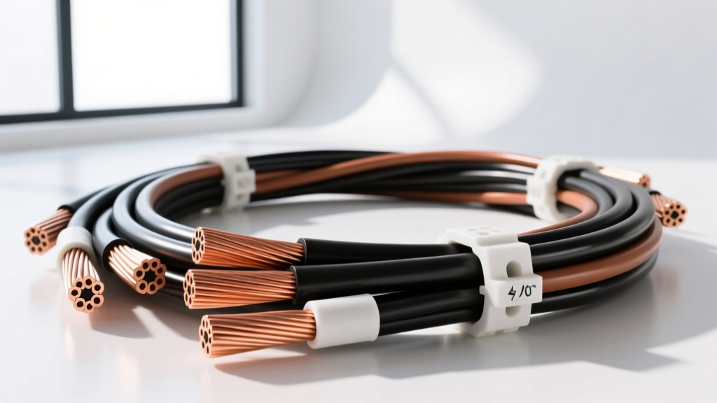
The AWG Inverse Scale: Defining the Thickest Wire Gauge
In the American Wire Gauge (AWG) system, wire thickness is inversely proportional to the gauge number. As the numerical value decreases, the cross-sectional area and current-carrying capacity of the conductor increase. When master technicians, EV conversion specialists, and heavy-duty fabricators ask what the thickest wire gauge is within the standard AWG framework, the definitive answer is 0000 AWG, universally written as 4/0 AWG.
While industrial and utility applications may utilize measured circular mils (kcmil or MCM) for conductors exceeding 4/0, the 4/0 AWG represents the absolute ceiling of the standard AWG logarithmic scale. In automotive, motorsport, marine, and commercial fleet applications, 4/0 AWG is the undisputed heavyweight champion of DC power transmission. It is the mandatory choice for high-amperage draws exceeding 250 amps continuously, such as heavy-duty winching systems, massive competition car audio alternators, and low-voltage side (12V/24V) EV battery interconnects.
4/0 AWG vs. Metric and kcmil: Heavy-Duty Cable Specifications
Understanding the physical and electrical properties of the thickest wire gauge requires examining its construction. Standard 4/0 AWG automotive battery cable (per SAE J1127) is typically stranded to balance flexibility with conductivity. However, for extreme articulation—such as in off-road rock crawlers using front-mounted winches or robotics—technicians utilize SGX (SGX battery cable) or premium ultra-flex welding cable.
Below is a technical comparison of the largest standard AWG and adjacent kcmil sizes used in high-current DC automotive and marine applications.
| Gauge Size | Cross-Sectional Area (mm²) | Circular Mils (cmil) | Typical Strand Count (Ultra-Flex) | Nominal Bare Diameter (in) | Resistance @ 20°C (Ω/1000 ft) | Max Ampacity (Chassis Wiring)* |
|---|---|---|---|---|---|---|
| 2/0 AWG | 67.43 | 133,100 | 1,330 x 30 AWG | 0.3648 | 0.1563 | 245 A |
| 3/0 AWG | 85.03 | 167,800 | 1,690 x 30 AWG | 0.4096 | 0.1239 | 285 A |
| 4/0 AWG | 107.22 | 211,600 | 2,107 x 30 AWG | 0.4600 | 0.0983 | 330 A |
| 250 kcmil | 126.67 | 250,000 | 2,470 x 30 AWG | 0.5000 | 0.0831 | 375 A |
*Note: Ampacity ratings for chassis wiring are based on single conductors in free air at an ambient temperature of 30°C, per standard marine and automotive derating curves. Bundling or routing through high-heat engine bays requires severe derating.
Automotive and EV Applications for 4/0 AWG
Heavy-Duty Winch and Recovery Systems
In off-road applications, a 16,500 lb winch (e.g., Warn 16.5ti) can pull upwards of 450 amps under maximum stall load. While the peak draw is brief, the voltage drop across undersized cables can starve the winch motor and overheat the solenoid. Utilizing 4/0 AWG SAE J1127 compliant EPDM (Ethylene Propylene Diene Monomer) insulated cable ensures minimal resistance. The standard color code for these DC recovery circuits is Red (positive) and Black (negative/ground).
Electric Vehicle (EV) Low-Voltage Busbars
While the high-voltage traction systems in modern EVs (400V to 800V architectures) utilize shielded, orange-jacketed (RAL 2003) cables governed by SAE J2840 and ISO 6722-1 standards, the 12V auxiliary systems and DC-DC converter feeds in custom EV conversions often require the thickest wire gauge available. Routing 4/0 AWG from the auxiliary lithium-iron-phosphate (LiFePO4) banks to the high-amperage inverter ensures the 12V side does not suffer brownouts when the electric power steering (EPS) and braking vacuum pumps cycle simultaneously.
Competition Car Audio and Alternator Upgrades
In SPL (Sound Pressure Level) competition vehicles, alternators capable of 350+ amps are common. The run from the alternator B+ terminal to the front distribution busbar demands 4/0 AWG oxygen-free copper (OFC) to handle the continuous high-amperage charging current without thermal degradation. Aluminum-clad copper (CCA) must be strictly avoided in these high-current, high-vibration environments due to its higher resistance and susceptibility to galvanic corrosion at the crimp lugs.
Termination and Crimping High-Current Thick Gauge Cables
Terminating the thickest wire gauge requires specialized tooling and meticulous technique. A standard hand-crimper is physically incapable of exerting the necessary force to cold-weld a 4/0 AWG lug to the copper strands. Failure to achieve a proper crimp results in increased contact resistance, leading to localized heating, insulation melt, and potential electrical fires.
Hydraulic Crimping and Die Selection
For 4/0 AWG, technicians must use a hydraulic crimper (minimum 8-ton to 12-ton force) equipped with precision hexagonal or indenter dies. According to Southwire's termination guidelines and UL standards, the crimp must compress the copper strands to eliminate all air pockets, forming a solid, gas-tight mass that prevents oxygen ingress and subsequent oxidation.
- Die Size: Match the die strictly to the lug manufacturer's specification (e.g., 1-1/16" hex die for a standard 4/0 AWG copper tube lug).
- Crimp Orientation: For multiple crimps on a single barrel, always start the crimp closest to the wire entry and work toward the tongue/pad.
- Inspection: A proper crimp will exhibit slight 'wings' or flash at the top of the hex profile, indicating the copper has completely filled the die cavity.
Environmental Sealing and Torque Specifications
Once crimped, the termination must be sealed against moisture and road salts. The industry standard is adhesive-lined, dual-wall polyolefin heat shrink tubing. The inner layer of hot-melt adhesive flows into the stranded wire capillary gaps, creating a watertight seal, while the outer layer provides abrasion resistance.
When bolting the 4/0 AWG lug to a busbar or battery terminal, torque specifications are critical. For an M10 (Grade 8.8) stainless steel or zinc-plated bolt securing a flat copper lug to a copper busbar, the target torque is typically 25 Nm (18.5 lb-ft). Under-torquing causes micro-arcing under high loads; over-torquing can stretch the bolt past its yield point, leading to a loss of clamping force as the copper cold-flows over time.
Voltage Drop Calculations for Maximum Thickness Cables
Even with the thickest wire gauge, voltage drop is an unavoidable reality of physics, governed by Ohm's Law. In a 12V automotive system, a voltage drop exceeding 3% (0.36V) across the main power delivery network is generally considered unacceptable for sensitive ECU and fuel pump circuits, though winch circuits can tolerate up to 5%.
Calculation Example:
Assume a 4/0 AWG copper cable run of 15 feet (total round-trip circuit length of 30 feet) powering a continuous 250A load (such as a heavy-duty hydraulic pump or continuous-duty inverter).
- Resistance of 4/0 AWG: 0.0983 Ω per 1,000 ft.
- Total Circuit Resistance: (30 ft / 1000) * 0.0983 = 0.002949 Ω.
- Voltage Drop: 250A * 0.002949 Ω = 0.737 Volts.
On a 12V system, a 0.737V drop represents a 6.1% loss, which is too high for continuous sensitive electronics but acceptable for a momentary winch pull. However, on a 48V heavy-duty truck architecture or a 400V EV system, that same 0.737V drop is mathematically negligible (less than 0.2%), highlighting why 4/0 AWG is highly efficient for higher-voltage DC platforms.
Troubleshooting High-Amperage Thick Cable Failures
When systems utilizing the thickest wire gauge experience faults, the failure rarely occurs in the middle of the cable span. Failures are almost exclusively localized to the terminations, routing points, or environmental breach zones. Use the following diagnostic framework when troubleshooting 4/0 AWG high-current circuits:
1. Thermal Runaway at the Lug
Symptom: Discolored heat shrink, melted lug insulation, or a distinct 'ozone/burning plastic' smell under heavy load.
Root Cause: Inadequate crimping force or using an undersized die, leaving voids inside the lug barrel. These voids increase resistance, generating heat (I²R losses). As the copper heats up, its resistance increases further, creating a thermal runaway loop.
Fix: Cut the compromised lug off. Strip back to clean, unoxidized copper. Verify strand count and re-crimp using a calibrated hydraulic tool and the correct hex die.
2. Galvanic Corrosion at Dissimilar Metal Junctions
Symptom: High resistance reading across the connection point; green/white powdery residue creeping out from under the heat shrink.
Root Cause: Connecting a tinned copper 4/0 AWG lug directly to an untreated aluminum busbar or chassis ground without dielectric isolation, exacerbated by moisture ingress.
Fix: Clean the mating surfaces with a brass wire brush. Apply a conductive antioxidant paste (e.g., Noalox or Penetrox) to inhibit oxidation and bridge microscopic gaps. Ensure all hardware is stainless steel or hot-dipped galvanized.
3. Strand Fatigue and Micro-Fractures
Symptom: Intermittent voltage drops that only occur when the vehicle suspension articulates or the engine torques over on its mounts.
Root Cause: Using standard-strand (SAE J1127) battery cable in an application requiring extreme continuous vibration or tight bend radii. The thick outer strands work-harden and snap, progressively reducing the effective cross-sectional area of the thickest wire gauge.
Fix: Replace the cable run with a high-strand-count (2,107+ strands) ultra-flex silicone or EPDM welding cable, and ensure the routing includes adequate service loops to absorb engine movement without placing tensile stress on the crimp joints.
For comprehensive safety standards regarding heavy-duty automotive cable, technicians should always consult the latest UL and SAE International documentation to ensure compliance with modern chassis wiring protocols.