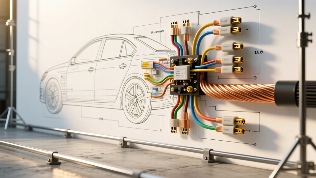
The Short Answer: What Gauge Is Telephone Wire?
When fabricators and DIY mechanics ask, what gauge is telephone wire, they are typically looking at standard indoor telecommunications cable (like Cat3 or flat station wire). The vast majority of traditional analog telephone wire is 24 AWG, though 22 AWG and 26 AWG variants also exist. This wire is almost exclusively manufactured with a solid copper core and a basic PVC (Polyvinyl Chloride) insulation jacket.
In the context of automotive upgrades and modification projects, builders frequently stumble upon spools of 24 AWG telephone wire in their garage and wonder if it can be used for low-amperage ECU sensor extensions, 5V reference lines, or CAN bus splicing. While the gauge (24 AWG) is mathematically correct for low-current data and thermistor signals, the physical construction of telephone wire makes it catastrophically unsuited for the harsh environment of a vehicle.
The DIY Trap: Why Builders Reach for Telecom Cable
When performing custom ECU installations (such as wiring a Haltech Elite or MoTeC M150), you need dozens of runs of small-diameter wire for sensors like the Intake Air Temperature (IAT), Coolant Temperature (CTS), and Throttle Position Sensor (TPS). These circuits typically carry less than 50 milliamps. According to standard ampacity charts, 24 AWG wire is more than sufficient to carry this current without significant voltage drop.
Because telephone wire is cheap, color-coded (often featuring white/blue, white/orange, white/green, and white/brown pairs), and readily available, it seems like the perfect candidate for custom harness building. However, using solid-core telecom wire in an automotive application is one of the most common mistakes in amateur harness fabrication, leading to intermittent faults, broken cores, and melted insulation.
Material Science: PVC vs. XLPE in the Engine Bay
To understand why telephone wire fails in cars, we must look beyond the AWG size and examine the metallurgy and insulation chemistry. Standard telephone wire uses solid copper and PVC. Solid copper has virtually zero flex life; the constant vibration of an internal combustion engine will cause solid-core wire to work-harden and snap inside the insulation. Furthermore, PVC insulation begins to soften and degrade at temperatures above 105°C (221°F). In an engine bay, exhaust manifolds and turbochargers easily push ambient under-hood temperatures past 120°C, causing PVC to melt, short out against the chassis, and destroy ECU drivers.
Automotive-grade wire, governed by the SAE J1128 standard, utilizes stranded copper (for vibration resistance) and Cross-Linked Polyethylene (XLPE) or Tefzel insulation. Materials like TXL (Thin-wall, Cross-linked) are rated for continuous use at 125°C and can withstand brief spikes up to 150°C, while resisting oil, brake fluid, and battery acid.
Comparison Chart: Telecom vs. Automotive 24 AWG
Below is a technical specification chart comparing standard 24 AWG telephone wire against the correct automotive alternatives for ECU sensor modifications.
| Specification | Standard Telephone Wire | SAE J1128 TXL (24 AWG) | MIL-W-22759/16 Tefzel (24 AWG) |
|---|---|---|---|
| Core Construction | Solid Copper | Stranded (19/36 or 7/32) | Stranded (19/36 Silver-Plated) |
| Insulation Material | PVC | XLPE (Cross-Linked PE) | ETFE (Tefzel) |
| Max Temp Rating | 60°C - 75°C | 125°C | 150°C - 200°C |
| Flex Life (Vibration) | Extremely Poor | Excellent | Superior |
| Chemical Resistance | Poor (Melts with solvents) | Good (Resists oil/acid) | Exceptional (Aerospace grade) |
| Automotive Suitability | DO NOT USE | Ideal for Engine Bay | Ideal for Firewall/Cockpit |
The CAN Bus Impedance Nightmare
Another common modification project involves extending or splicing into a vehicle's CAN bus network to integrate aftermarket digital dashes or telemetry modules. Some builders attempt to use Cat5 or twisted-pair telephone wire for CAN High (CAN H) and CAN Low (CAN L) lines because it is already twisted.
This is a critical error. The ISO 11898-2 standard for high-speed CAN bus requires a characteristic impedance of 120 ohms. Standard telecommunications cable (like Cat5e) is manufactured to a 100-ohm impedance specification. While 100-ohm cable might work on a bench, the impedance mismatch in a noisy automotive environment causes signal reflections. When combined with the lack of proper braided shielding found in dedicated automotive CAN cable (like MIL-SPEC shielded twisted pair), the ECU will inevitably experience CAN bus-off states, throwing U-codes and disabling critical systems like electronic throttle control or ABS.
Project Guide: Properly Extending a Bosch IAT Sensor
Instead of telephone wire, let us outline the correct procedure for extending a low-amperage sensor circuit using proper 24 AWG automotive wire. In this scenario, we are relocating a standard Bosch 2-pin Intake Air Temperature (IAT) sensor to a new cold-air intake plenum.
Required Materials and Pinout
- Wire: 24 AWG TXL (Primary Automotive Wire, Stranded).
- Colors: Pin 1 (Signal) - White/Blue Trace; Pin 2 (Sensor Ground) - Black/White Trace.
- Connector: TE Connectivity (Tyco) 2-Pin Superseal 1.5 or Bosch EV1/Jetronic.
- Pins: Superseal female terminals with silicone weather seals.
- Splicing: Solder-seal heat shrink butt connectors (Raychem SolderSleeve) or Deutsch crimp tools.
Step-by-Step Execution
- Measure and Cut: Cut two lengths of 24 AWG TXL wire. Add 10% extra length to account for drip loops and strain relief near the intake manifold.
- Strip and Crimp: Strip exactly 4mm of insulation. Use a ratcheting crimp tool (like the Delphi Packard crimp die) to attach the weather-sealed pins. The wire brush crimp must grip the copper strands, while the insulation crimp grips the XLPE jacket.
- Seal the Connections: Slide the silicone weather seals over the wire before crimping. Push them into the connector housing until they click, ensuring the IP67 waterproof barrier is established.
- Splice to Factory Harness: Do not use twist-ties or electrical tape. Use adhesive-lined, solder-seal heat shrink connectors. Apply heat until the solder ring melts and the adhesive oozes from the ends, creating a hermetic seal against moisture and corrosion.
- Loom and Secure: Wrap the extended harness in split corrugated loom or Tesa tape. Secure the harness to the chassis using P-clips with rubber cushions, ensuring the wire does not rest against sharp brackets or hot exhaust components.
Troubleshooting Signal Noise and Voltage Drop
Even when using the correct 24 AWG TXL wire, improper routing can introduce noise into sensitive 5V reference circuits. Thermistors (like IAT and CTS sensors) operate on a voltage divider circuit. The ECU sends a 5V reference through a pull-up resistor, and the sensor grounds the circuit through a variable resistor that changes with temperature.
If you route your 24 AWG sensor wires parallel to high-current ignition coils or fuel injector harnesses, Electromagnetic Interference (EMI) can induce a false voltage in the signal wire. The ECU will interpret this noise as a fluctuating temperature, causing erratic fuel trims and idle surging.
The Fix: Always route low-voltage 24 AWG sensor wires at a strict 90-degree angle to high-current 12V or 14 AWG injector/coil wires. If parallel routing is unavoidable, maintain a minimum separation distance of 2 inches, or upgrade the sensor extension to a 24 AWG shielded twisted pair, grounding the shield drain wire at the ECU end only to prevent ground loops.
Summary: Leave the Telecom Wire in the House
So, what gauge is telephone wire? It is usually 24 AWG, which is the correct cross-sectional area for automotive ECU data and sensor lines. However, the solid-core construction and low-temperature PVC insulation make it a liability in any vehicle modification project. By investing in SAE J1128 compliant TXL wire, proper ratcheting crimpers, and sealed automotive connectors, you ensure that your custom harness will survive the thermal cycling, vibration, and chemical exposure of the engine bay, delivering clean, reliable data to your ECU for years to come.