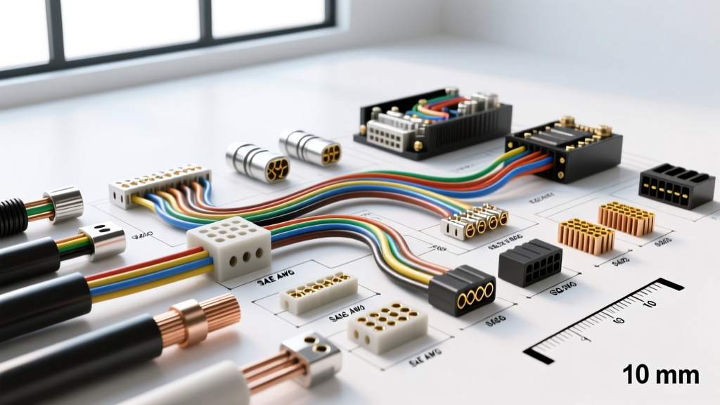
The Core Conflict: SAE J1128 vs. ISO 6722 Standards
When performing a detailed wire gauge comparison for modern automotive platforms, technicians quickly realize that simply matching diameters is a recipe for electrical failure. The global automotive industry operates on two primary wiring standards: the American Wire Gauge (AWG) system governed by SAE J1128, and the metric cross-sectional area system governed by ISO 6722. While a 16 AWG wire and a 1.0mm² ISO wire are often used interchangeably in aftermarket harnesses, their stranding architectures, insulation thicknesses, and thermal tolerances differ significantly.
SAE J1128 defines insulation types like GXL (thin-wall, 125°C) and TXL (extra-thin-wall, 125°C), which prioritize maximum copper volume in tight engine bays. Conversely, ISO 6722 classifications like FLRY (thin-wall PVC) and FLR (thin-wall polyolefin) dictate specific strand counts that alter the wire's flexibility and voltage drop characteristics over long chassis runs. A true wire gauge comparison must account for these metallurgical and chemical differences, not just the physical outer diameter.
Comprehensive Wire Gauge Comparison Chart
The following reference table bridges the gap between AWG and Metric sizing, providing critical data for chassis wiring and power transmission. Note that ampacity ratings assume a single wire in free air at an ambient temperature of 30°C (86°F). Bundled harnesses require severe derating, which we will address later.
| AWG Size | ISO Metric (mm²) | Nominal OD (in / mm) | Copper Area (cmil) | Max Ampacity (Chassis) | Typical Automotive Application |
|---|---|---|---|---|---|
| 22 AWG | 0.35 mm² | 0.051 / 1.30 | 642 | 7A | CAN Bus Data, OBD2 Pins 6/14 |
| 20 AWG | 0.50 mm² | 0.064 / 1.63 | 1020 | 10A | MAP Sensors, 5V Reference Lines |
| 18 AWG | 0.75 mm² | 0.079 / 2.00 | 1624 | 16A | Injector Pigtails, Interior Lighting |
| 16 AWG | 1.00 mm² | 0.094 / 2.39 | 2583 | 22A | Fuel Pump Relays, Horn Circuits |
| 14 AWG | 1.50 mm² | 0.109 / 2.77 | 4107 | 32A | Headlight Power, Ignition Coils |
| 12 AWG | 2.50 mm² | 0.128 / 3.25 | 6530 | 45A | EFI Main Relays, Cooling Fans |
| 10 AWG | 4.00 mm² | 0.155 / 3.94 | 10380 | 60A | Alternator B+ Output (Stock) |
| 4 AWG | 16.00 mm² | 0.252 / 6.40 | 41740 | 150A | High-Amp Alternator Upgrades |
| 1/0 AWG | 50.00 mm² | 0.398 / 10.11 | 105600 | 250A | EV Inverter Cables, Starter Solenoids |
High-Current Applications: EV Inverters and Starter Circuits
When routing high-amperage cables for EV battery interconnects or LS-swap starter solenoids, the wire gauge comparison shifts from simple conductivity to thermal mass and crimping mechanics. A common mistake is using standard SAE battery cable (which features a coarse, stiff strand count) in tight-radius chassis bends. This causes the copper to work-harden and fracture inside the insulation.
For high-vibration, high-current applications, specify fine-strand welding cable or ISO Class 6 (FLR6) metric cable. For example, upgrading a GM 1-Wire alternator to a 250A Powermaster unit requires stepping up from the factory 4 AWG to a 1/0 AWG (or 50mm²) fine-strand cable. When terminating these heavy cables to a power distribution busbar, use closed-barrel hex crimps rather than indent crimps. Hex crimps distribute mechanical stress evenly across all copper strands, preventing the 'onion peeling' effect that causes high-resistance hot spots.
Hardware Torque Specifications for Heavy Lugs
- M8 (5/16-inch) Stud: 18-22 Nm (13-16 lb-ft) using a flange hex nut.
- M10 (3/8-inch) Stud: 25-30 Nm (18-22 lb-ft) using a Belleville (conical) spring washer to maintain tension during thermal expansion cycles.
Data and Sensor Networks: The Micro-Wire Paradigm
In the realm of CAN bus networks and ECU sensor inputs, physical wire gauge is secondary to impedance, shielding, and twist rates. A standard OBD2 diagnostic port utilizes 22 AWG (0.35mm²) wire for the high-speed CAN network. Specifically, Pin 6 (CAN-H) and Pin 14 (CAN-L) must be routed as a shielded twisted pair with a twist rate of at least 1 twist per inch to reject electromagnetic interference (EMI) from ignition coils and alternator ripple.
When repairing a severed CAN bus harness, never splice in unshielded 20 AWG or 18 AWG wire just because it is more durable. The larger diameter alters the characteristic impedance of the circuit, which must remain strictly at 120 ohms. Splicing in the wrong gauge causes signal reflection, resulting in U-codes (e.g., U0100 Lost Communication with ECM) that only appear when the engine is running and EMI is highest. Always use 22 AWG (0.35mm²) shielded twisted pair, and terminate the splice with adhesive-lined dual-wall heat shrink and a solder sleeve.
Voltage Drop and Thermal Derating in Bundled Harnesses
According to standard ampacity charts, a 12 AWG wire can handle 45 amps in free air. However, automotive wiring is rarely in free air. When you bundle 15 wires together inside a corrugated split-loom and route them through a sealed firewall grommet, the ambient temperature inside that bundle can easily exceed 60°C (140°F) due to mutual resistive heating.
The Derating Rule: For every 5 wires bundled together in a conduit, you must derate the ampacity of the entire bundle by 20%. If your electric cooling fan draws 35 amps, and the wiring is routed through a dense 20-pin bulkhead connector alongside fuel pump and A/C clutch circuits, your 12 AWG wire is effectively derated to roughly 30 amps. The wire will overheat, melting the plastic terminal housing inside the bulkhead connector. In dense harnesses, always step up one full gauge size (e.g., use 10 AWG for a 35A load) to compensate for thermal bundling.
Troubleshooting Decision Tree: Mismatched Gauge Failures
Mismatched wire gauges often present as intermittent electrical gremlins or catastrophic connector meltdowns. Use this diagnostic tree to identify gauge-related failures:
- Symptom: Fuel pump relay socket is melted, but the relay itself tests fine.
- Cause: The installer used 18 AWG (0.75mm²) wire on Pin 87 (Load) to feed a high-flow Bosch 044 fuel pump drawing 18-22 amps under pressure. The 18 AWG wire acts as a resistor, generating heat that transfers backward into the relay spade terminals.
- Fix: Replace the pigtail with a ceramic high-temp relay socket wired with minimum 14 AWG (1.50mm²) TXL wire, and upgrade the inline fuse to 25A.
- Symptom: Wideband O2 sensor reads erratic AFRs only at high RPM.
- Cause: The sensor ground wire was spliced into a shared 20 AWG (0.50mm²) ECU sensor ground that is also carrying the return load for the MAP and TPS sensors. The cumulative voltage drop on the shared micro-wire skews the 5V reference.
- Fix: Run a dedicated 16 AWG (1.00mm²) ground wire directly from the wideband controller to a clean, unpainted cylinder head stud, bypassing the shared ECU ground plane entirely.
Expert Insights on Connector Compatibility
When transitioning between AWG and metric wire, terminal crimp compatibility becomes a major hurdle. TE Connectivity and Delphi (Aptiv) design their Metri-Pack 150 and 280 series terminals for specific insulation and copper diameters. If you attempt to crimp an ISO 0.50mm² wire into a terminal designed for 20 AWG, the insulation crimp wings may not fully engage the jacket, leading to wire pull-out under vibration. Always verify the wire cross-section against the terminal manufacturer's application tooling chart, and use a ratcheting crimp tool calibrated to the exact AWG/mm² specification to ensure a gas-tight, cold-weld connection.