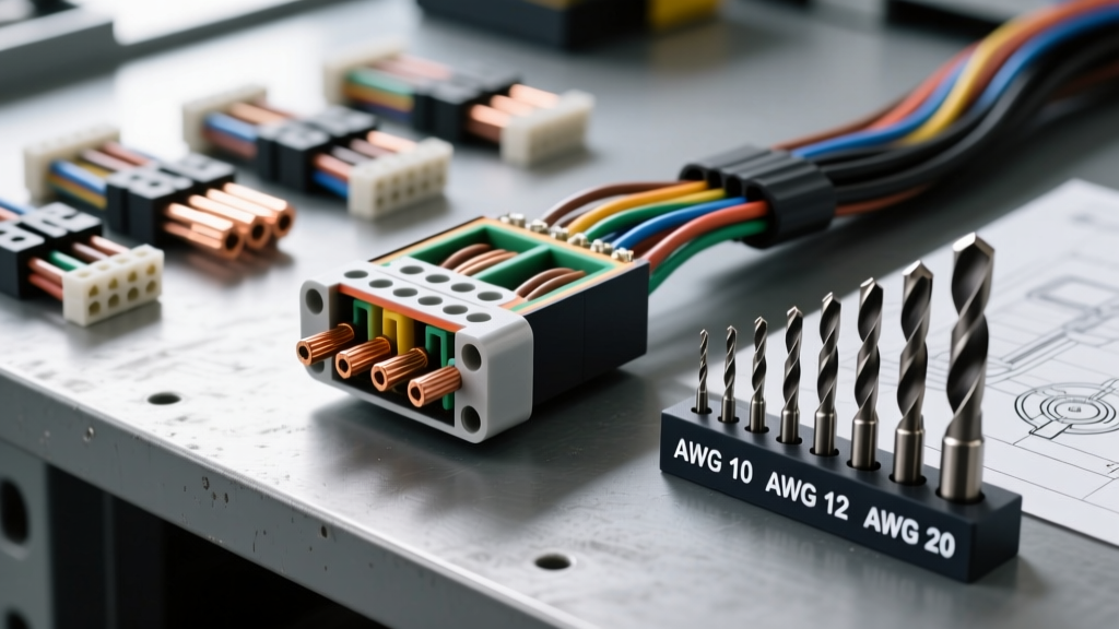
The Intersection of AWG Sizing and Number-Gauge Drill Bits
In automotive electrical engineering and harness fabrication, the term wire gauge drill bits refers to the critical practice of cross-referencing American Wire Gauge (AWG) conductor and insulation diameters with number, letter, or fractional drill bit sizes. While AWG strictly defines the cross-sectional area of the bare copper conductor (per ASTM B3 standards), automotive technicians must account for the outer diameter (OD) of the insulation—typically TXL, GXL, or SXL—when drilling bulkhead pass-throughs, sizing firewall grommets, or clearing debris from multi-pin connector cavities.
Using a standard fractional drill bit set often leads to oversized firewall holes, resulting in poor grommet seating, water intrusion into the cabin, and harness chafing. Conversely, using undersized bits causes insulation tear-through during wire pulling. By leveraging precision number-gauge drill bits (ranging from #80 to #1) and letter-gauge bits (A to Z), harness builders can achieve exact tolerances for specific automotive wire types.
Cross-Reference Chart: AWG Wire to Drill Bit Sizing
The following reference table maps standard automotive primary wire sizes (SAE J1128) to their bare copper diameters, typical GXL insulation outer diameters, and the closest matching number or letter-gauge drill bit. This chart is essential for selecting the correct bit for single-wire cavity clearing or precision grommet hole drilling.
| AWG Size | Bare Copper Dia. (in) | GXL Insulation OD (in) | Closest Number/Letter Drill Bit | Bit Decimal Equivalent (in) | Primary Automotive Application |
|---|---|---|---|---|---|
| 18 AWG | 0.0403 | 0.071 | #50 (or 1/16" for bundle) | 0.0700 | Sensor signals, CAN bus, injector pigtails |
| 16 AWG | 0.0508 | 0.090 | #43 | 0.0890 | Lighting circuits, relay triggers |
| 14 AWG | 0.0641 | 0.110 | #34 | 0.1110 | Accessory power, horn circuits |
| 12 AWG | 0.0808 | 0.135 | #29 | 0.1360 | Fuel pump feeds, high-draw lighting |
| 10 AWG | 0.1019 | 0.165 | #20 | 0.1610 | Ignition feeds, ECU main power |
| 8 AWG | 0.1285 | 0.205 | #3 (or Letter B) | 0.2130 | Alternator outputs, starter solenoids |
| 4 AWG | 0.2043 | 0.325 | Letter Q | 0.3320 | Main battery cables, high-amperage inverters |
Note: Always verify the specific insulation type. SXL insulation features a thicker wall than GXL, requiring an adjustment of 1 to 2 drill bit sizes larger on the number gauge scale.
Bulkhead Pass-Through Engineering and Packing Factors
When routing a harness through a vehicle firewall, you are rarely drilling for a single wire. Harness bundles require calculating the circumscribed circle diameter to select the proper step bit or letter-gauge drill bit. Automotive harnesses do not pack perfectly; the industry-standard packing factor for a bundle of 3 to 7 wires is approximately 0.70 to 0.75.
Calculating Bundle Drill Size
To determine the correct drill bit size for a bulkhead hole, use the following methodology:
- Sum the cross-sectional area of all wires in the bundle using their insulation OD.
- Divide by the packing factor (0.70) to account for air gaps and wire crossing.
- Calculate the diameter of the resulting area.
- Round up to the nearest standard letter-gauge or fractional drill bit size to allow for grommet compression.
For example, a bundle containing four 18 AWG wires and two 12 AWG wires requires a hole size that accommodates the larger 12 AWG wires' bending radius. A 5/8" (0.625") or Letter W (0.386" - too small, use fractional here) step bit is typically employed, followed by a ribbed EPDM firewall grommet rated for 0.625" to 0.687" panel thickness.
Terminal Cavity Maintenance: The Drill Bit Shank Technique
One of the most valuable, yet least documented, uses of wire gauge drill bits in automotive diagnostics is the clearing of blocked terminal cavities in sealed connectors like the Delphi Weather-Pack, TE Connectivity AMPSEAL, or Deutsch DT/HD series. Over time, silicone cavity plugs degrade, and road grime packs into unpopulated cavities, preventing the insertion of new terminals.
Why Fluted Bits Destroy Connectors
Never use the cutting flutes of a drill bit to clean a connector cavity. The flutes will easily shave away the delicate plastic retention tangs or score the silicone wire seal mating surface, leading to immediate capillary water intrusion. Instead, expert technicians use the smooth shank of a number-gauge drill bit matched to the AWG wire size.
- Deutsch DT (Size 16 Cavities): Use the shank of a #34 drill bit (0.111"). The smooth shank pushes out hardened debris and degraded silicone plugs without damaging the internal stainless steel retention spring.
- Weather-Pack (Size 16/14 Cavities): Use the shank of a #29 bit (0.136") to clear the secondary lock ramp debris.
- Metri-Pack 280 Series: Use the shank of a #20 bit (0.161") for safe cavity clearing.
According to TE Connectivity application specifications, maintaining the integrity of the cavity's primary and secondary lock geometry is mandatory for maintaining the 135N minimum terminal retention force.
Real-World Application: GM LS-Swap O2 Sensor Harness Routing
Consider a common aftermarket scenario: routing a Bank 1 Oxygen Sensor harness through the passenger side firewall of a GM LS-swapped vehicle. The harness consists of four 18 AWG TXL wires.
Pinout and Wire Color Specifications (GM LS1/LS2 Standard)
- Pin A: Dark Blue (Low Signal)
- Pin B: Purple/White (High Signal)
- Pin C: Black (Low Reference/Ground)
- Pin D: Tan (Heater Control)
Because these are 18 AWG TXL wires, the bare copper is 0.0403", but the TXL insulation OD is approximately 0.071". The total bundle diameter is roughly 0.160". To drill the firewall pass-through, a technician should select a #12 drill bit (0.216") or a 7/32" (0.218") fractional bit. This provides exactly enough clearance to pull the harness through a 1/4" ID silicone bulkhead grommet without stretching or tearing the TXL insulation against the raw steel edge of the firewall.
After drilling, the hole must be deburred using a stepped countersink to prevent the grommet from being sliced during installation or by engine bay vibration, adhering to the chafing prevention guidelines outlined in SAE J1128 Low Tension Primary Cable standards.
Troubleshooting Wire Pull and Grommet Failures
| Symptom | Probable Cause (Drill/Gauge Mismatch) | Technical Fix |
|---|---|---|
| Grommet pushes into cabin under vacuum | Drill bit oversized; hole exceeds grommet's maximum panel grip range. | Switch to a smaller letter-gauge bit or use a two-part epoxy-sealed marine grommet. |
| Insulation strips off wire during pull | Drill bit undersized; metal burr left on firewall edge. | Ream hole with next size up number-gauge bit and deburr both sides. |
| Terminal won't click into Deutsch cavity | Debris in cavity; fluted drill used, destroying retention tang. | Replace connector body. Use smooth drill shank for future cavity clearing. |
| Water leaks through bulkhead after rain | Packing factor miscalculated; bundle too loose in grommet ID. | Fill void space with marine-grade dielectric grease or RTV silicone. |
Authoritative References & Standards
Precision in automotive wiring requires adherence to established engineering standards. When selecting wire gauge drill bits and sizing harness pass-throughs, always consult the following resources:
- SAE International J1128: Defines the physical dimensions, insulation thickness, and thermal ratings for low-tension primary automotive cables.
- IPC-A-620: The industry standard for cable and wire harness assemblies, detailing acceptable hole-to-wire clearance ratios and grommet installation practices.
- ASTM B3: Standard Specification for Soft or Annealed Copper Wire, providing the baseline mathematical constants for bare AWG conductor diameters.
By treating drill bit selection as an extension of wire gauge specification, technicians can eliminate harness failures at the bulkhead, ensuring long-term reliability in harsh automotive environments.