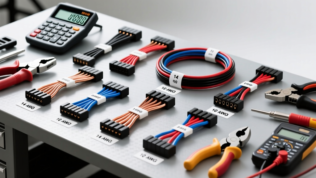
The Physics of Parallel Automotive Wiring
When upgrading high-draw automotive systems—such as installing a 250A alternator for a winch setup, running EV battery swap busbars, or wiring a 3000W car audio amplifier—technicians often face a physical limitation: routing a single, massive 1/0 AWG or 2/0 AWG cable through a tight factory firewall grommet or along a congested frame rail. The solution is running parallel conductors. However, you cannot simply guess the equivalent thickness. Using a combined wire gauge calculator allows you to determine the exact Circular Mil (CM) equivalency of multiple smaller wires run in parallel, ensuring your total cross-sectional area can handle the target amperity without exceeding voltage drop thresholds.
The fundamental rule of parallel wiring is that the total Circular Mils of the combined wires must equal or exceed the Circular Mils of the single target wire. Furthermore, according to NFPA 70 (NEC) Article 310.10(G) and standard SAE J1128 automotive electrical practices, parallel conductors must be identical in length, material (Oxygen-Free Copper), stranding, and termination method to prevent 'current hogging,' where one wire carries a disproportionate amount of the load and overheats.
Combined Wire Gauge Calculator: Circular Mil Reference Chart
Below is a reference chart generated from standard combined wire gauge calculator formulas. This chart translates parallel AWG runs into their single-wire AWG equivalents based on total cross-sectional area.
| Target Single AWG | Target Circular Mils (CM) | Equivalent Parallel Run (Wire Size x Quantity) | Combined CM | Ampacity Rating (Chassis Wiring) |
|---|---|---|---|---|
| 1/0 AWG | 105,600 | Dual 4 AWG | 83,480 (Close to 1 AWG) | ~150A per run (300A Total) |
| 2/0 AWG | 133,100 | Dual 2 AWG | 132,720 | ~190A per run (380A Total) |
| 4 AWG | 41,740 | Dual 8 AWG | 33,020 (Close to 5 AWG) | ~60A per run (120A Total) |
| 8 AWG | 16,510 | Dual 12 AWG | 13,100 (Close to 9 AWG) | ~40A per run (80A Total) |
Note: Always use 100% Oxygen-Free Copper (OFC). If forced to use Copper-Clad Aluminum (CCA), you must upsize each parallel leg by two AWG sizes to compensate for CCA's 40% higher electrical resistance.
Cost Analysis: Single Heavy-Gauge vs. Parallel Runs
Is running parallel wires actually cheaper? Let us analyze the cost and tool requirements for a 15-foot alternator-to-battery positive run targeting a 250A capacity (requiring 1/0 AWG equivalent). We will compare a single 1/0 AWG run against a dual 4 AWG parallel run.
Material Cost Breakdown
| Component | Single 1/0 AWG Run | Dual 4 AWG Parallel Run |
|---|---|---|
| Wire Cost (OFC) | $67.50 (15ft @ $4.50/ft) | $54.00 (30ft total @ $1.80/ft) |
| Terminations (Lugs) | $6.00 (Two 1/0 single-hole lugs) | $24.00 (Four 4AWG dual-hole lugs) |
| Heat Shrink & Sealant | $4.00 | $8.00 |
| Zip Ties & Loom | $10.00 | $15.00 (Requires larger split loom) |
| Total Estimated Cost | $87.50 | $101.00 |
The Verdict: A combined wire gauge calculator might suggest dual 4 AWG is a perfect physical substitute, but material costs are actually higher due to the premium price of dual-hole parallel lugs and the doubled termination labor. The true value of parallel wiring in automotive applications is not cost savings; it is routing flexibility. Two 4 AWG wires can easily bend through a 1.5-inch firewall grommet, whereas a stiff 1/0 AWG cable often requires drilling a new, larger pass-through hole.
Tool Requirements for High-Amp Parallel Crimping
Executing a parallel wire run requires specialized tooling. Standard pliers-based crimpers will not achieve the necessary cold-weld compression for high-amperage circuits.
- Hydraulic Crimper with Hex Dies: A 12-ton hydraulic crimper (such as the Channellock 499 or Knoweasy equivalent) is mandatory. Hex dies compress the copper strands into a solid, uniform mass, eliminating air pockets where galvanic corrosion begins.
- Dual-Hole Copper Lugs: Never stack two single-hole lugs on a single alternator stud. Stacking creates a micro-gap between the lugs that traps moisture and increases resistance. You must use specialized dual-hole parallel lugs (e.g., ILSCO or Panduit dual-hole compression lugs) where both 4 AWG wires are crimped into a single barrel that splits into two parallel ring terminals.
- Adhesive-Lined Polyolefin Heat Shrink: Standard PVC heat shrink is insufficient. You must use 3:1 ratio, dual-wall adhesive-lined heat shrink. When heated, the inner thermoplastic adhesive melts and wicks into the copper strands, creating a watertight seal that prevents capillary action from pulling battery acid or road salt into the wire barrel.
- Wire Stripper with V-Notch: Standard automatic strippers often nick the outer strands of 4 AWG wire, reducing the cross-sectional area and creating a localized hot spot. Use a V-notch manual stripper or a specialized heavy-gauge cable peeler.
Real-World Application: 250A Alternator Upgrade (LS Swap)
Consider a common scenario: swapping a high-output Powermaster 250A alternator into a classic muscle car during an LS engine swap. The factory 10-gauge alternator wire will instantly melt under a 200A+ load. Using our combined wire gauge calculator logic, we route dual 4 AWG red OFC cables from the alternator output stud to a front-mounted 250A ANL fuse block, and then to the battery positive terminal.
Execution Specifications
- Termination at Alternator: The Powermaster utilizes an M8 (8mm) threaded output stud. Torque the dual-hole 4 AWG lug nut to exactly 12-15 Nm (8-11 lb-ft). Over-torquing can strip the brass internal threads of the alternator diode bridge; under-torquing will cause micro-arcing that welds the lug to the stud.
- Routing & Looming: Both parallel wires must be routed identically. If Wire A runs near the exhaust header and Wire B runs near the cold fender well, Wire A will experience higher ambient heat, increasing its resistance. Current will shift to Wire B, potentially overloading it. Zip-tie both wires together every 6 inches and encase them in a shared high-temp fiberglass split loom.
- Sense Wire Calibration: High-output alternators require a dedicated 10 AWG sense wire run directly to the battery positive. Do not rely on the factory sense wire, as the voltage drop across the new parallel main cables will cause the alternator to overcharge the battery to compensate for perceived line loss.
Troubleshooting Decision Tree: Parallel Circuit Failures
Even with a perfect combined wire gauge calculation, parallel circuits can fail if execution is flawed. Use this diagnostic tree when troubleshooting high-amp electrical gremlins:
- Symptom: Alternator output drops to 12.5V under heavy load (winching/audio), and one of the parallel wires is noticeably hotter to the touch than the other.
- Cause: Current Hogging due to unequal crimp compression or unequal wire length.
- Fix: Cut off both lugs. Measure both wires to ensure they are within 0.25 inches of each other in length. Re-crimp using a calibrated hydraulic die. Verify resistance across both wires with a milliohm meter; they must match within 0.001 ohms.
- Symptom: Green/white crusty corrosion appears at the crimp joint after 6 months, leading to voltage drop.
- Cause: Moisture wicking. Standard heat shrink was used, or the adhesive-lined shrink was not heated from the middle outward.
- Fix: Cut the terminal. Clean the copper with electrical contact cleaner. Re-crimp and apply 3:1 adhesive heat shrink, heating from the center of the barrel outward to push the molten adhesive out the edges, sealing the strand gaps.
- Symptom: Melted plastic around the alternator output stud, but the wires themselves are cool.
- Cause: Stacked lugs or improper torque on the M8 stud, causing terminal resistance rather than wire resistance.
- Fix: Replace stacked lugs with a single dual-hole parallel lug. Clean the stud threads with a brass wire brush. Torque to 12-15 Nm using a calibrated inch-pound torque wrench.
By leveraging a combined wire gauge calculator and strictly adhering to these tool and termination requirements, you can safely execute parallel wiring runs that match or exceed the reliability of single, heavy-gauge cables while solving complex automotive routing challenges.