The Hidden Danger of Guessing Wire Gauge in Automotive Mods
When planning an automotive electrical upgrade—whether you are installing a high-output alternator, a 1000W car audio amplifier, or a heavy-duty winch—the most critical question you must answer is: how do I know what gauge wire I have already in my vehicle? Splicing a massive 4 AWG aftermarket power cable into an undersized 10 AWG OEM harness is a recipe for catastrophic voltage drop, melted insulation, and potential electrical fires. Automakers design wiring harnesses to handle specific stock loads with minimal overhead. To safely execute an upgrade, you must accurately identify the existing factory wire gauge before cutting, splicing, or adding new terminals.
Method 1: Decoding OEM Insulation Printing and Color Codes
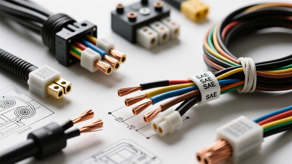
The most non-destructive way to identify your wire gauge is by inspecting the insulation. Under the SAE J1128 Standard for Low Tension Cable, manufacturers are required to print specifications directly onto the wire jacket. Strip back a few inches of the factory split-loom tubing and look for a sequence of raised or printed text.
You will typically see a designation like "12 GXL" or "10 TXL". Here is what those letters mean for your modification project:
- GXL: General purpose, thin-wall insulation. Rated for 125°C. Common in modern engine bays where space and heat are factors.
- TXL: Extra-thin wall insulation. Rated for 125°C. Used in tight harness wraps. The copper conductor is the same size as GXL, but the outer diameter is smaller.
- SXL: Standard (thick) wall insulation. Rated for 125°C. Often found in heavy-duty truck applications or high-vibration zones where abrasion resistance is critical.
If the printing is worn off due to engine bay heat and oil exposure, you can cross-reference the wire color and circuit function with a factory service manual. For example, on a GM LS-based V8, the main alternator output wire to the battery is typically a heavy-gauge Red wire, while the Ford 3G alternator output often utilizes a Yellow/Light Green or Black/Orange 6 AWG wire.
Method 2: The Digital Caliper and Strand-Count Method
When printing is illegible, you must measure the bare copper conductor. Never measure the wire with the insulation on. AWG (American Wire Gauge) and SAE sizing strictly measure the cross-sectional area of the conductive metal, not the plastic jacket. Measuring the outside diameter of a thick-walled SXL wire will trick you into thinking you have a much larger gauge than you actually do.
Step-by-Step Caliper Measurement
- Strip the Wire Safely: Use a precision wire stripper to remove 1 inch of insulation. Do not nick the copper strands; nicking reduces the effective cross-sectional area and creates a high-resistance hot spot.
- Compress the Strands: Twist the stranded copper tightly so there are no air gaps between the strands.
- Measure the Diameter: Use digital calipers to measure the outer diameter of the bare copper bundle in millimeters (mm).
- Count the Strands: Fan out the wire and count the individual copper strands. Automotive wire is highly standardized by strand count.
Automotive Wire Gauge Specification Chart
Use the reference table below to match your caliper measurements and strand counts to the correct gauge. Note the critical difference between AWG (American Wire Gauge) and SAE (Society of Automotive Engineers) sizing. SAE wire is slightly smaller in diameter than AWG for the same gauge number to account for the higher conductivity of modern automotive copper alloys.
| Gauge Size | AWG Diameter (mm) | SAE Diameter (mm) | Standard Strand Count | Max Ampacity (105°C) | Common Mod Application |
|---|---|---|---|---|---|
| 4 AWG | 5.19 mm | 4.88 mm | 133 | 120A | Winch power, Big 3 Upgrade |
| 8 AWG | 3.26 mm | 3.05 mm | 49 | 73A | OEM Alternator Output, Audio Amps |
| 10 AWG | 2.59 mm | 2.44 mm | 30 | 55A | Cooling fan relays, Fuel pumps |
| 12 AWG | 2.05 mm | 1.93 mm | 19 | 41A | Headlight power feeds, Horns |
| 14 AWG | 1.63 mm | 1.52 mm | 19 | 32A | LED Light bar triggers, Accessory |
| 16 AWG | 1.29 mm | 1.19 mm | 26 | 22A | Interior switches, ECU sensors |
Reference data adapted from the Wire and Cable To Go Master Gauge Chart and SAE J1128 specifications.
Real-World Mod Scenarios: Identifying and Upgrading
Scenario A: The "Big 3" Alternator Upgrade
You are upgrading a Chevrolet Silverado from a stock 105A alternator to a 250A high-output unit to support off-road lighting and a winch. You need to upgrade the alternator-to-battery positive cable. First, you must identify the OEM wire. Peeling back the corrugated loom near the alternator B+ terminal, you find a Red wire with no legible printing. Using calipers on the bare copper, you measure a diameter of 3.20mm and count roughly 49 strands. According to our chart, this is an 8 AWG (or 8 SAE) wire.
The Fix: An 8 AWG wire is only rated for roughly 73 amps. Pushing 250 amps through it will cause severe voltage drop and melt the insulation. You must bypass or replace this OEM wire with a minimum of 1/0 AWG OFC (Oxygen-Free Copper) welding cable, terminating it with a heavy-duty 5/16" ring terminal crimped using a hydraulic crimper, and sealed with adhesive-lined heat shrink.
Scenario B: Auxiliary LED Light Bar Relays
You are wiring a 30-inch LED light bar on a Jeep Wrangler JK. The plan is to use the factory auxiliary switch bank to trigger a 40A automotive relay. You need to know what gauge wire is running from the switch to the relay coil (Pin 85/86). You strip back the harness and measure 1.50mm with 19 strands. This confirms it is 14 AWG.
The Fix: 14 AWG is more than sufficient to trigger a standard 40A Bosch-style relay coil, which draws less than 200mA. However, you must ensure your connector matches the wire. If you are using a Delphi Weather-Pack 150 series connector for the relay pigtail, the 150 series terminals are specifically designed to crimp onto 14-16 AWG wire insulation and conductors. Attempting to force 14 AWG wire into a Weather-Pack 280 series terminal (designed for 10-12 AWG) will result in a loose crimp, arcing, and eventual relay failure.
Why Conductor Material Matters in Upgrades
When replacing the OEM wire you just identified, pay strict attention to the conductor material of your aftermarket wire. Many cheap automotive wiring kits sold online use CCA (Copper-Clad Aluminum). CCA wire has a higher electrical resistance than pure OFC (Oxygen-Free Copper). If you replace an OEM 8 AWG copper wire with an 8 AWG CCA wire, you are effectively downgrading the current-carrying capacity by nearly 15%. For high-current modifications like audio amplifiers or winch solenoids, always verify that your replacement wire is stamped as 100% OFC to match or exceed the factory SAE specifications.