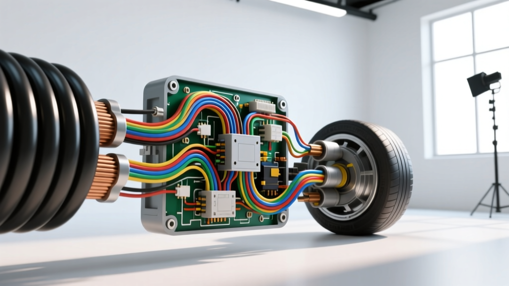
The 'Large Gauge' Paradox: Understanding AWG Inversion
When automotive enthusiasts and junior technicians begin upgrading high-current circuits—such as alternator outputs, winch feeds, or overland solar banks—they frequently encounter a dangerous linguistic trap: the phrase 'large gauge wire.' In the American Wire Gauge (AWG) system, the physical diameter of the conductor is inversely proportional to its numerical gauge size. Therefore, a 'larger' wire physically is actually a smaller AWG number. A 1/0 AWG (often written as 0 AWG) cable is significantly thicker and carries more current than a 4 AWG cable. Misunderstanding this inversion is the first step toward catastrophic electrical failure, undersized cabling, and potential vehicle fires.
Upgrading to heavy-duty cabling requires strict adherence to SAE J1128 standards for low-tension primary cables, alongside rigorous attention to termination, fusing, and routing. Below, we detail the most critical safety warnings and common mistakes made when working with heavy-duty automotive cabling.
Mistake #1: Undersizing Fuses for High-Ampacity Cables
The primary purpose of a fuse is to protect the wire, not the component. A prevalent and highly dangerous mistake is pairing a massive over-current protection device (OCPD) with an inadequately sized cable. For example, installing a 250-amp ANL fuse on a 4 AWG battery cable to protect a heavy-duty winch circuit.
The Thermal Runaway Hazard
Under continuous load, a 4 AWG copper wire with standard PVC insulation (rated for 90°C) has an ampacity of roughly 60 to 70 amps in an engine bay environment where ambient temperatures already exceed 50°C. If a winch stalls and draws 200 amps, the 250-amp ANL fuse will not blow. Instead, the 4 AWG wire becomes the fuse. The PVC insulation will melt, short against the chassis, and ignite surrounding components.
- Correction: Always size the fuse based on the wire's ampacity, not the load's peak draw. If the load requires 250 amps, you must upgrade to 2/0 AWG cross-linked polyethylene (XLPE) wire, which can safely handle the current, and pair it with a 250A Class T or Mega fuse.
- Proximity Rule: The OCPD must be installed within 18 inches of the positive battery terminal. If the wire between the battery and the fuse shorts to ground, it is completely unfused and will weld itself to the chassis.
Mistake #2: Soldering vs. Crimping Heavy-Duty Terminals
While soldering is acceptable for small-gauge, low-current signal wires, it is a severe safety hazard for large gauge wire (typically 8 AWG and thicker). The misconception that 'solder makes a better electrical connection' ignores the mechanical realities of a vibrating vehicle chassis.
The Capillary Wicking Effect
When you apply heat and solder to a heavy-duty ring terminal on a 2 AWG cable, capillary action wicks the molten solder deep into the copper strands. This transforms a highly flexible, stranded copper cable into a rigid, solid copper rod at the termination point. Under engine vibration, the mechanical stress concentrates exactly at the boundary where the flexible wire meets the rigid solder joint. This inevitably leads to work hardening, copper fatigue, and a complete strand fracture.
Proper Termination Protocol
According to marine and automotive electrical best practices outlined by authorities like Blue Sea Systems, heavy-duty cables must be cold-crimped.
- Strip the Wire: Use a rotary cable stripper to avoid nicking the outer copper strands. Never use a standard pinch-style stripper on 4 AWG or larger.
- Use Hex Dies: For large gauge wire, indent-style crimpers are insufficient. You must use a 12-ton hydraulic crimper with hex dies. Hex dies compress the terminal uniformly around the entire circumference, ensuring maximum surface area contact without deforming the terminal's mounting ring.
- Seal the Joint: Slide dual-wall, adhesive-lined heat shrink over the terminal before crimping. When heated, the inner polyamide adhesive melts and flows into the copper strands, creating a waterproof seal that prevents galvanic corrosion and copper oxidation (the green crust that increases resistance).
Mistake #3: Ignoring Voltage Drop in Long Runs
Wire size must be calculated based on both ampacity (heat) and voltage drop. A cable might be thick enough not to melt, but if it is too long, the resistance will cause a massive voltage drop, starving the component of the power it needs to operate efficiently.
Below is a reference chart demonstrating the voltage drop in a standard 12.6V automotive charging system over a 10-foot round-trip circuit (5 feet positive, 5 feet negative) at a continuous 100-amp load.
| Wire Size (AWG) | Resistance per 1,000 ft | Voltage Drop (at 100A / 10ft run) | Resulting Voltage at Load | Safety Verdict |
|---|---|---|---|---|
| 4 AWG | 0.2485 Ω | 0.497 V | 12.10 V | Marginal for continuous 100A |
| 2 AWG | 0.1563 Ω | 0.312 V | 12.28 V | Acceptable for most 12V loads |
| 1/0 AWG | 0.0983 Ω | 0.196 V | 12.40 V | Excellent / Heavy Duty |
| 2/0 AWG | 0.0779 Ω | 0.155 V | 12.44 V | Required for Inverters/Winches |
Note: For 24V systems or sensitive ECU power feeds, the allowable voltage drop is typically capped at 1% to 2%. Always upsize your large gauge wire when the run exceeds 15 feet.
Mistake #4: Improper Torque and Battery Terminal Oxidation
When terminating large gauge wire to battery posts or high-current busbars, technicians often rely on 'feel' rather than a calibrated torque wrench. This leads to two distinct failure modes:
- Under-torquing: Creates high contact resistance. As current flows through the high-resistance joint, it generates immense heat (following Joule's Law, P = I²R). This heat expands the metal, loosening the bolt further in a thermal runaway cycle that eventually melts the terminal.
- Over-torquing: Strips the threads on busbars, cracks cast lead battery posts, or deforms the copper ring terminal, reducing the physical contact patch.
Specification: Most heavy-duty automotive battery terminal clamps require between 90 and 120 in-lbs (inch-pounds, NOT foot-pounds) of torque. Always apply a thin layer of dielectric antioxidant compound (such as NO-OX-ID A-Special) to the terminal faces after crimping but before final assembly to prevent micro-arcing and oxidation.
Safety Warning: Routing and Chafing Hazards
Heavy-gauge cabling is stiff and difficult to bend, which often leads to lazy routing decisions. The insulation on standard large gauge wire (even XLPE) will melt instantly if draped over an exhaust manifold or sharp aluminum bracket.
Firewall and Chassis Pass-Throughs
Never pass large gauge wire through bare sheet metal. Engine vibration will saw through the thickest insulation in a matter of miles, creating a dead short to the chassis. You must use heavy-duty rubber firewall grommets or dedicated marine deck glands. If the wire must pass near heat sources (exhaust headers, turbochargers), it must be sleeved in fiberglass fire-sleeve or high-temperature silicone loom rated for continuous 500°F exposure.
Troubleshooting Decision Tree: Heavy Cable Failures
When diagnosing issues related to large gauge wire installations, use this symptom-cause-fix framework:
- Symptom: Intermittent clicking from the starter solenoid, but battery tests at 12.6V at the posts.
Cause: Voltage drop across a corroded or under-crimped positive battery terminal.
Fix: Cut off the old terminal, strip back to clean copper, re-crimp with a hydraulic hex die, and torque to 110 in-lbs. - Symptom: Discoloration or melting of the wire insulation near the alternator output stud.
Cause: Use of standard PVC-insulated wire in an ambient environment exceeding 105°C, or undersized wire for a high-output (e.g., 200A+) alternator.
Fix: Replace the run with 2 AWG or 1/0 AWG wire featuring XLPE (Cross-Linked Polyethylene) insulation, rated for 125°C continuous, and ensure a Mega fuse is installed at the battery end. - Symptom: Winch operates sluggishly and battery cables become too hot to touch under load.
Cause: Undersized ground path. Many installers upgrade the positive feed to 2/0 AWG but leave the factory 4 AWG chassis ground strap.
Fix: The ground return path must be equal to or greater than the positive feed. Install a matching 2/0 AWG ground cable directly from the winch motor housing to the engine block or negative battery terminal.
Working with large gauge wire demands respect for electrical physics. By avoiding these common mistakes, utilizing proper hydraulic crimping tools, and adhering to strict fusing and routing protocols, you ensure your vehicle's high-current systems remain safe, efficient, and reliable under the harshest conditions.