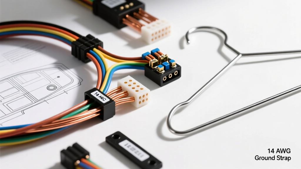
The Core Question: What Gauge Wire Is a Clothes Hanger?
In automotive garages and DIY welding setups, a frequent question arises during makeshift repairs or ground strap fabrications: what gauge wire is a clothes hanger? To answer this from a strict dimensional perspective, a standard wire coat hanger is manufactured from low-carbon steel wire with a typical diameter ranging from 2.0 mm to 2.3 mm. According to the American Wire Gauge (AWG) standard, a 2.05 mm diameter equates to 12 AWG, while a 2.30 mm diameter equates to 11 AWG. Heavy-duty commercial hangers can reach 2.6 mm, which aligns with 10 AWG.
However, in automotive electrical systems, physical diameter is only half the equation. The fundamental flaw in using a clothes hanger as a ground strap, jumper wire, or welding return cable lies in its metallurgical composition. While a 12 AWG copper wire is a standard for moderate-load automotive circuits, a 12 AWG steel hanger possesses vastly different electrical characteristics that can lead to catastrophic voltage drops, phantom ECU codes, and severe fire hazards.
The Metallurgical Catch: Steel vs. Copper Conductivity
Electrical conductivity is measured against the International Annealed Copper Standard (IACS), where pure copper is rated at 100%. Low-carbon steel, the material used in clothes hangers, typically operates at only 10% to 15% IACS. This means steel is roughly 6 to 8 times more resistive than copper. Therefore, a 12 AWG steel clothes hanger electrically behaves like a 21 or 22 AWG copper wire. If you attempt to route starter motor return current (often exceeding 150 amps) through a steel hanger, the immense resistance will cause the wire to glow red-hot, melt surrounding insulation, and fail to crank the engine.
Step-by-Step Troubleshooting Flow: Diagnosing the 'Hanger Hack'
When diagnosing electrical gremlins—such as dimming headlights, slow cranking, or erratic sensor readings (e.g., P0122 Throttle Position Sensor Low Voltage)—technicians must verify the integrity of the vehicle's grounding points. Follow this step-by-step troubleshooting flow to identify and rectify makeshift ground failures.
Step 1: Visual Identification of Makeshift Grounds
Begin with a thorough visual inspection of common grounding locations where previous owners or inexperienced mechanics might have substituted a factory braided ground strap with a clothes hanger or generic steel wire.
- Engine Block to Chassis/Firewall: Critical for ECU grounding and alternator return. Look for bare steel wire wrapped around exhaust manifold bolts or hood hinges.
- Battery Negative to Fender Well: Often compromised by battery acid corrosion, leading to DIY replacements using whatever wire is on hand.
- Transmission Bellhousing to Block: Essential for starter motor return paths. A steel hanger here will bottleneck the high-amperage cranking circuit.
Red Flag Indicators: Look for signs of galvanic corrosion (white, powdery aluminum oxide or severe orange rust) at the termination points. Steel and aluminum (such as an LS engine block) create a galvanic cell in the presence of moisture, rapidly increasing contact resistance.
Step 2: The Voltage Drop Test (Loaded Circuit)
Never rely on a standard ohmmeter to test a ground; a single strand of 12 AWG steel can show continuity (near 0 ohms) on a multimeter but will fail under a 50-amp load. You must perform a dynamic voltage drop test.
- Setup: Set your Digital Multimeter (DMM) to DC Volts. A true-RMS automotive meter like the Fluke 88V is recommended.
- Probe Placement: Connect the DMM's black lead directly to the battery's negative post (not the terminal clamp). Connect the red lead to the metal casing of the component you are testing (e.g., the alternator housing or engine block).
- Apply Load: Have an assistant crank the engine or turn on high-draw accessories (headlights, blower motor, rear defroster).
- Interpret Results: According to AutoShop101 electrical diagnostic standards, a healthy automotive ground circuit should exhibit a voltage drop of less than 0.10V (100mV) under load. If your meter reads 0.50V or higher across a suspected steel hanger ground, the wire is acting as a massive resistor and must be replaced immediately.
Step 3: Thermal Imaging and Resistance Verification
If the voltage drop test indicates a fault but the exact location is hidden behind skid plates or inner fenders, use a thermal imaging camera (such as a FLIR ONE) while the circuit is under load. A high-resistance steel hanger ground will generate significant heat due to I²R (I-squared-R) power losses. The wire or its termination ring will appear as a bright white/yellow hotspot on the thermal display, confirming the exact point of failure.
Automotive Ground Wire Specifications & Sizing Chart
When replacing a makeshift clothes hanger ground, you must select the correct AWG based on the circuit's maximum amperage. The chart below contrasts the physical and electrical properties of standard steel hangers against proper Oxygen-Free Copper (OFC) automotive ground cables.
| Material & Type | AWG Size | Diameter (mm) | Resistance (Ohms/1000ft) | Max Ampacity (Automotive) | Recommended Application |
|---|---|---|---|---|---|
| Steel Clothes Hanger | 12 AWG (Nominal) | 2.30 | ~10.50 (Estimated) | 5A - 8A | Exhaust hangers, mechanical tie-downs ONLY |
| OFC Copper Wire | 12 AWG | 2.05 | 1.588 | 20A - 25A | ECU grounds, sensor shields, lighting returns |
| OFC Copper Wire | 8 AWG | 3.26 | 0.628 | 50A - 60A | Alternator grounding, fuel pump relays |
| OFC Copper Wire | 4 AWG | 5.18 | 0.248 | 120A - 150A | Engine block to chassis, battery main ground |
| OFC Copper Wire | 2/0 AWG | 9.26 | 0.077 | 250A - 300A | Starter motor return, high-output welding grounds |
Note: Ampacity ratings vary based on ambient temperature and wire bundling. Always adhere to SAE J378 Recommended Practice for Wiring for high-amperage DC circuits.
Corrective Action: Proper Ground Strap Installation
Once the faulty steel hanger has been removed, follow these precise installation steps to ensure a permanent, low-resistance ground path.
1. Surface Preparation
Resistance at the termination point is often higher than the wire itself. Use a 3M Roloc bristle disc or a wire wheel to strip away all paint, powder coating, and rust from the chassis or engine block down to bare, shiny metal. The contact patch should be slightly larger than the outer diameter of the ring terminal.
2. Terminal Selection and Crimping
Do not use solder on high-amperage ground connections; solder can melt under extreme fault currents and has higher resistance than a proper mechanical crimp. Select a tinned copper, closed-barrel ring terminal (e.g., Ancor Marine Grade). Use a 12-ton hydraulic crimper with the correct hexagonal die (usually marked for the specific AWG) to cold-weld the terminal to the wire strands. Seal the joint with adhesive-lined heat shrink tubing to prevent moisture ingress and subsequent green-copper corrosion.
3. Hardware and Torque Specifications
Replace any corroded factory bolts with high-grade hardware (Grade 8 or stainless steel, depending on the application). Apply a thin layer of conductive anti-oxidant compound (like Noalox) between the terminal and the bare metal surface to block oxygen and moisture. Torque the fastener to the manufacturer's specification. For example, an M8x1.25 bolt tapped into an aluminum engine block should typically be torqued to 20-25 Nm (15-18 lb-ft), while an M10 bolt into a steel chassis rail should be torqued to 40-45 Nm (30-33 lb-ft).
4. Post-Installation Verification
Repeat the loaded voltage drop test. A properly installed 4 AWG OFC ground strap utilizing bare-metal contact and anti-oxidant paste should yield a voltage drop reading of 0.01V to 0.03V even during heavy engine cranking.