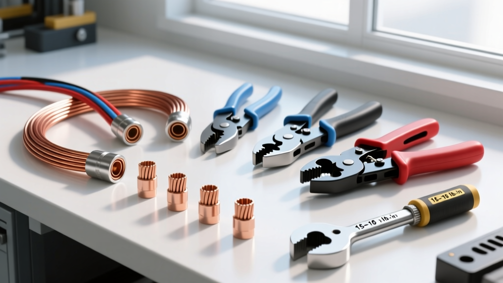
The Physics of High-Current 6 AWG Terminations
When routing high-amperage circuits in automotive applications—such as alternator upgrades, EV battery management systems, or heavy-duty winch feeds—6 AWG wire is the industry baseline. Capable of carrying 120A continuously under SAE J1128 high-temperature engine bay ratings, the wire itself is rarely the failure point. The vulnerability lies entirely in the 6 gauge wire connectors and the termination methodology.
A poorly crimped 6 AWG terminal introduces micro-gaps that increase electrical resistance. According to Joule's First Law (P = I²R), even a marginal increase in resistance at a 100-amp draw will generate catastrophic heat, melting polyolefin insulation and causing voltage drop cascades. This advanced deep dive explores the metallurgy, crimping geometries, and SAE-compliant termination protocols required for 6 AWG automotive circuits.
Metallurgy and Connector Selection
Copper vs. Aluminum Terminals
For automotive 6 AWG applications, electrolytic tough pitch (ETP) copper terminals are mandatory. Avoid aluminum or copper-clad aluminum (CCA) connectors. CCA connectors suffer from galvanic corrosion when mated to copper wire, creating aluminum oxide—a highly resistive compound that leads to thermal runaway.
Always select connectors rated for SAE J1292 Automotive Electrical Terminals. These terminals feature a specific annealing process that allows the barrel to deform uniformly around the 6 AWG stranding (typically 133/0.010" or 259/0.010" tinned copper) without work-hardening and cracking.
Terminal Geometries for High-Amperage
- Ring Terminals (Stud Mount): The gold standard for alternator B+ terminals and starter solenoids. For 6 AWG, use a barrel length of at least 0.625 inches to ensure adequate surface area.
- Anderson SB50 / Powerpole: Ideal for removable winch connections and auxiliary battery trays. The SB50 housing utilizes roll-pin retention and silver-plated copper contacts to handle 120A continuous draw.
- Butt Splices (Stepped Barrel): Use only for joining two 6 AWG runs. Must feature a brazed seam to prevent the barrel from opening under heavy hydraulic crimp pressure.
Crimp vs. Solder: The SAE Mandate
A persistent myth in aftermarket wiring is that soldering 6 AWG connections is superior. In automotive environments subject to high vibration and thermal cycling, solder is a liability. Solder wicks into the wire strands via capillary action, creating a rigid stress point just outside the connector barrel. Under engine vibration, the wire fractures at this rigid-to-flexible transition.
The correct methodology is a gas-tight mechanical crimp. A proper hex-crimp compresses the copper strands and the terminal barrel into a single solid mass, displacing oxygen and preventing corrosion while maintaining flexibility. For comprehensive wire specifications, refer to the Ancor Technical Information Guide, which aligns with marine and heavy-duty automotive SAE standards.
Thermal Derating and Voltage Drop Mathematics
Automotive wiring guides often cite the NEC ampacity charts, but these assume ambient room temperatures. In an engine bay, ambient temperatures routinely exceed 105°C (221°F). According to SAE J1128 standards, the resistance of copper increases linearly with temperature. At 20°C, 6 AWG copper exhibits a resistance of 0.3951 ohms per 1,000 feet. At 105°C, this resistance spikes to approximately 0.513 ohms per 1,000 feet.
If you are routing a 10-foot 6 AWG alternator charge wire (20 feet total circuit length out and back) carrying 120A, the voltage drop calculation is:
V_drop = Current × (Resistance_per_ft × Total_Length)
V_drop = 120A × (0.000513 ohms/ft × 20 ft) = 1.23 Volts.
A 1.23V drop in a 14.4V charging system leaves only 13.17V reaching the battery. This is why high-output alternator upgrades often mandate stepping up to 4 AWG or 2 AWG, or utilizing dual 6 AWG runs in parallel to halve the resistance and mitigate voltage drop.
6 AWG Termination Specification Chart
| Parameter | Specification / Requirement | Engineering Notes |
|---|---|---|
| Wire Strip Length | 0.65" - 0.75" (16.5mm - 19mm) | Strands must not extend past the inspection hole; insulation must not enter the crimp barrel. |
| Crimp Die Profile | Hexagonal (Hex) or F-Type | Hex dies provide 360-degree uniform compression, essential for high-strand-count 6 AWG flex wire. |
| Minimum Pull-Out Force | 150 lbs (667 N) | Per SAE terminal pull-test standards for 6 AWG conductors. |
| Heat Shrink Ratio | 3:1 Dual-Wall Adhesive Polyolefin | Inner adhesive layer melts to seal against moisture and battery acid intrusion. |
Step-by-Step High-Amperage Crimping Protocol
Executing a flawless termination on 6 gauge wire connectors requires specialized tooling. Standard pliers or hammer-crimpers are entirely insufficient for 6 AWG and will result in high-resistance hot spots.
- Stripping: Use a precision wire stripper with a 6 AWG specific bore. Do not use a utility knife, which will nick the tinned copper strands, reducing the cross-sectional area and creating a localized resistance point.
- Wire Brushing: Lightly brush the exposed copper strands with a stainless-steel wire brush to remove surface oxidation. Apply a micro-drop of conductive anti-oxidant paste (e.g., Noalox) if mating to aluminum busbars.
- Insertion & Alignment: Insert the wire into the terminal barrel until it bottoms out. Ensure the insulation jacket sits flush against the bellmouth of the barrel.
- Hydraulic Crimping: Place the terminal in a 6 AWG hex crimp die (typically marked "16mm2" or "6" on ratcheting tools like the IWISS HX-6). Squeeze until the ratchet releases. The resulting hex profile should have sharp, defined corners with no copper extrusion.
- Adhesive Sealing: Slide a 3:1 dual-wall heat shrink tube over the connection. Apply heat starting from the middle and moving outward to force air and excess adhesive out the ends, creating a waterproof environmental seal.
Torque Specifications and Stud Mating
The termination is only half the battle; the mechanical mating of the 6 AWG ring terminal to the component stud dictates the long-term reliability of the circuit. Under-torquing leads to micro-arcing and stud welding; over-torquing strips threads or snaps the stud.
- 5/16" Stud (e.g., Starter Solenoid, Fuse Block): 13 - 15 ft-lbs.
- 3/8" Stud (e.g., Alternator B+, Distribution Block): 20 - 25 ft-lbs.
- 1/2" Stud (e.g., Winch Solenoid, Main Battery Post): 35 - 40 ft-lbs.
Pro-Tip: Always use a hardened steel flat washer and a split-lock washer (or Nord-Lock wedge-locking washers in high-vibration diesel applications) to maintain clamping force as the copper terminal undergoes thermal expansion and contraction.
Diagnostic Troubleshooting: Thermal and Voltage Signatures
When diagnosing failing 6 gauge wire connectors, visual inspection is rarely sufficient until catastrophic melting occurs. Utilize the following diagnostic matrix:
1. Infrared Thermography
Under a sustained 80A+ load (e.g., winching or high-output audio system draw), scan the connector with an FLIR thermal camera. A healthy crimp will show a temperature delta of less than 5°C compared to the wire insulation. A delta exceeding 15°C indicates internal strand fracture or inadequate barrel compression.
2. Millivolt Drop Testing
Set a digital multimeter to the DC millivolt (mV) range. Place the positive probe on the wire side of the crimp and the negative probe on the ring terminal eye. Under load, a reading above 10mV (0.010V) per connection indicates a failing 6 AWG termination that requires immediate replacement. For more advanced testing protocols and TE Connectivity terminal specifications, always cross-reference manufacturer application guides.