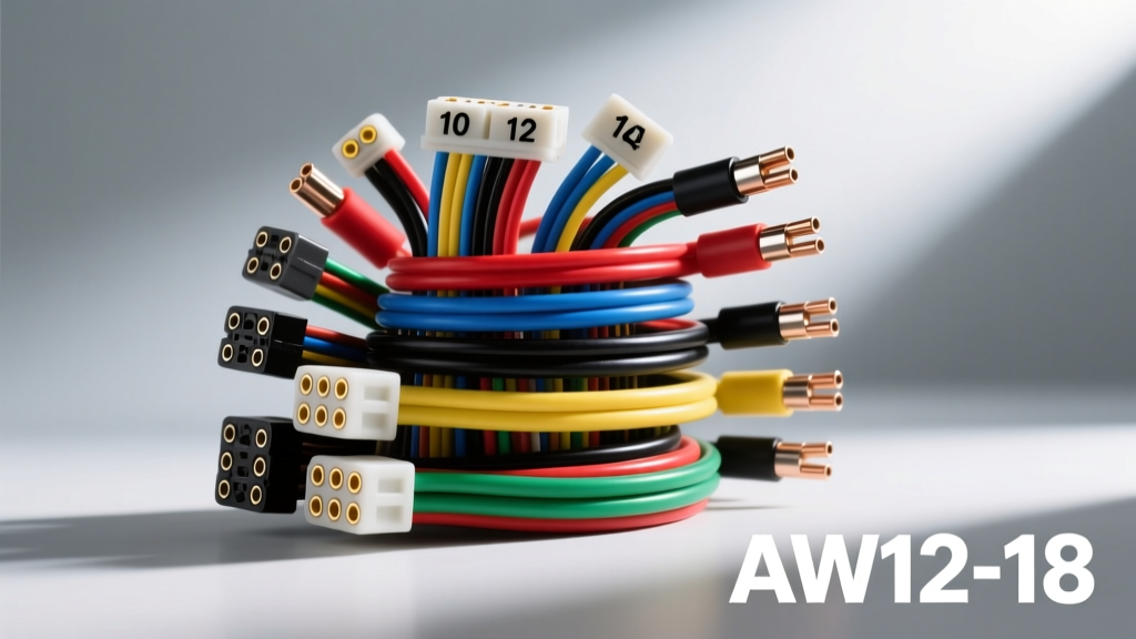
Understanding AWG Wire Gauge in Automotive Electrical Systems
The American Wire Gauge (AWG) system is the foundational standard for sizing electrical conductors in North American automotive applications. Defined by the ASTM B258 standard specification, the AWG scale is logarithmic and inverse: as the gauge number decreases, the physical cross-sectional area and current-carrying capacity (ampacity) increase. Unlike residential wiring which utilizes solid core conductors, automotive environments demand highly flexible, multi-strand copper wire to withstand constant chassis vibration, thermal expansion cycles, and tight routing radii.
When selecting the correct AWG wire gauge for a vehicle build, restomod, or harness repair, technicians must look beyond simple amperage. The SAE J1128 Low Tension Primary Cable Standard dictates that automotive wire must meet strict insulation requirements for heat, abrasion, and chemical resistance. Standard PVC household wire will melt and short-circuit in an engine bay; therefore, automotive-grade cross-linked polyethylene (XLPE) insulations such as TXL, GXL, and SXL are mandatory for under-hood routing.
Comprehensive AWG Wire Gauge Specification Chart
The following reference table outlines the physical dimensions, DC resistance, and maximum ampacity ratings for standard copper automotive wire at an ambient temperature of 20°C (68°F). Note that "Chassis Wiring" ampacity applies to short runs in free air, while "Power Transmission" applies to bundled harnesses or enclosed looms where heat dissipation is restricted.
| AWG Size | Nominal Diameter (in) | Cross Section (mm²) | Max Amps (Chassis) | Max Amps (Bundled) | Ohms per 1,000 ft (Cu @ 20°C) |
|---|---|---|---|---|---|
| 18 AWG | 0.0403 | 0.82 | 16 A | 3 A | 6.385 |
| 16 AWG | 0.0508 | 1.31 | 22 A | 4 A | 4.016 |
| 14 AWG | 0.0641 | 2.08 | 32 A | 5.9 A | 2.525 |
| 12 AWG | 0.0808 | 3.31 | 41 A | 9.3 A | 1.588 |
| 10 AWG | 0.1019 | 5.26 | 55 A | 15 A | 0.9989 |
| 8 AWG | 0.1285 | 8.37 | 73 A | 24 A | 0.6282 |
| 6 AWG | 0.1620 | 13.3 | 101 A | 37 A | 0.3951 |
| 4 AWG | 0.2043 | 21.1 | 125 A | 60 A | 0.2485 |
| 2 AWG | 0.2576 | 33.6 | 170 A | 94 A | 0.1563 |
| 1/0 AWG | 0.3249 | 53.5 | 195 A | 125 A | 0.0983 |
| 4/0 AWG | 0.4600 | 107.0 | 260 A | 195 A | 0.0490 |
SAE Metric vs. AWG: Navigating Modern Vehicle Harnesses
While domestic and older import vehicles rely heavily on AWG, modern European and Asian platforms utilize the ISO 6722 metric standard, measured in square millimeters (mm²). When repairing a late-model harness or integrating an aftermarket ECU (like a MoTeC or Haltech) into a factory chassis, you must map metric wire to the nearest AWG equivalent.
- 0.50 mm²: Equivalent to 20 AWG. Used for low-current sensor signals (e.g., MAP, IAT, TPS).
- 0.80 mm²: Equivalent to 18 AWG. Standard for injector control wires and low-draw lighting.
- 1.50 mm²: Equivalent to 16 AWG. Used for ignition coils and moderate-load solenoids.
- 2.50 mm²: Equivalent to 13 AWG (use 12 AWG). Common for fuel pump feeds and headlight power circuits.
- 4.00 mm²: Equivalent to 11 AWG (use 10 AWG). Found in high-draw cooling fan circuits and ABS pump feeds.
Connector Terminal Compatibility by AWG Size
Selecting the correct AWG wire gauge is only half the battle; the wire must properly mate with the terminal crimp barrel of your chosen connector. Utilizing an undersized wire in a large terminal barrel causes high-resistance cold joints, while forcing oversized wire leads to crushed strands and structural failure.
Delphi Weatherpack & Metripack Series
- Weatherpack (Green/Red Terminals): Designed for 18-14 AWG wire. Ideal for exterior lighting and accessory switches.
- Weatherpack (Blue Terminals): Designed for 12-10 AWG wire. Used for high-current relays, horns, and fuel pump pigtails.
- Metripack 1.5: Accepts 20-16 AWG. The standard for modern ECU sensor harnesses.
- Metripack 2.8: Accepts 16-12 AWG. Used for power distribution blocks and high-current actuator feeds.
Deutsch DT & DTM Series
Deutsch connectors utilize a unified Size 16 pin and socket system, which accommodates a broad range of 20 to 14 AWG wire. For motorsport applications where 14 AWG is too thick for the high-density DTM layout, technicians often use 16 AWG wire but must ensure the wire seal and crimp tool are strictly calibrated for 16 AWG to prevent the wire from pulling out under vibration.
Calculating Voltage Drop in EFI and High-Draw Circuits
A common failure mode in aftermarket EFI (Electronic Fuel Injection) conversions is fuel pump starvation caused by excessive voltage drop. Fuel pumps require a minimum of 13.5V at the pump terminals to maintain adequate rail pressure under wide-open throttle (WOT). If the wiring is undersized, resistance increases, voltage drops, and the pump starves the engine, leading to catastrophic detonation.
Use the following voltage drop formula to size your wire:
V_drop = (2 × L × R × I) / 1000
Where L = one-way length in feet, R = resistance per 1,000 ft (from the chart above), and I = current draw in Amps.
Example Scenario: A 255 LPH fuel pump drawing 15A, located 12 feet from the front-mounted battery.
- Using 16 AWG (R = 4.016): V_drop = (2 × 12 × 4.016 × 15) / 1000 = 1.44 Volts. (Unacceptable; pump receives only ~12.5V).
- Using 10 AWG (R = 0.9989): V_drop = (2 × 12 × 0.9989 × 15) / 1000 = 0.35 Volts. (Excellent; pump receives ~13.8V).
Always calculate voltage drop using the total round-trip distance (positive and ground wires). According to the NFPA 70 National Electrical Code guidelines adapted for low-voltage DC systems, a maximum voltage drop of 3% is recommended for critical engine management circuits.
High-Current Routing: Alternators, Starters, and Winches
For high-amperage components, the AWG scale transitions into zero-gauge sizing (1/0, 2/0, 4/0). Upgrading a factory 80A alternator to a 200A unit to support car audio, lighting, or dual EFI setups requires upgrading the main charge wire.
- 140A - 175A Alternators: Require a minimum of 4 AWG or 2 AWG welding cable.
- 200A+ Alternators: Require 1/0 AWG to prevent thermal runaway in the charge wire.
- Starter Motors: Draw 250A to 400A+ under cranking load. Use 1/0 AWG or 2/0 AWG fine-strand battery cable.
- Winches (10,000+ lbs): Can draw 500A+ at stall. Mandates 4/0 AWG wire routed directly to the battery, bypassing any chassis grounding to prevent frame welding.
Crimping Standards: High-current AWG lugs (such as ANL fuse holders or Mega fuse terminals) must be crimped using a hydraulic crimper with hexagonal or indent dies. Mechanical ratcheting crimpers often fail to compress the deep core strands of 1/0 or 4/0 wire, leaving air pockets that oxidize and create high-resistance hot spots. Always seal the crimp barrel with adhesive-lined dual-wall heat shrink to prevent moisture ingress and copper oxidation.
Real-World Failure Modes and Derating Factors
Automotive electrical systems are hostile environments. When applying the AWG ampacity chart, you must apply derating factors for specific conditions:
- Engine Bay Heat Derating: If routing wire within 6 inches of exhaust headers or turbochargers, ambient temperatures can exceed 120°C. Even SXL wire (rated to 125°C) will experience increased resistance. Derate the ampacity by 30% and utilize fiberglass braided sleeving or reflective heat shields.
- Harness Bundling Derating: When wrapping 10+ wires into a single loom, the inner wires cannot dissipate heat. The NFPA 70 National Electrical Code recommends derating bundled wire ampacity by up to 50%. Always use the "Bundled" column in the specification chart above for main harness trunks.
- High-Resistance Grounds: A 10 AWG power wire is useless if the ground path relies on a rusty chassis bolt. For any circuit drawing over 15A (e-fans, fuel pumps, ECU main relays), run a dedicated 10 AWG or 8 AWG ground wire directly back to the battery negative terminal or a clean, dedicated chassis bus bar.
By strictly adhering to AWG specifications, utilizing proper automotive-grade insulation, and calculating voltage drop for critical circuits, you ensure the longevity and reliability of the vehicle's entire electrical architecture.