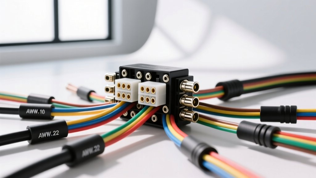
Understanding Housing Wire Gauge in Automotive Electrical Systems
When building or repairing automotive wiring harnesses, the term housing wire gauge refers to the critical intersection between the American Wire Gauge (AWG) size of your primary cable, the metal crimp terminal, and the plastic connector housing cavity. Selecting the correct housing wire gauge is not merely about current capacity; it is about physical compatibility. If you attempt to force a 12 AWG wire into a connector housing engineered for 18 AWG terminals, the terminal will not seat, the insulation will crush, or the secondary lock will fail, leading to catastrophic moisture ingress and eventual short circuits.
As automotive electrical systems evolve to handle higher current loads for accessories like fuel pumps, electric fans, and high-output alternators, understanding how to properly match your wire gauge to your connector housing is a fundamental skill. This practical installation guide will walk you through the exact specifications, crimping techniques, and housing selections required for reliable, OEM-grade automotive wiring.
The Anatomy of a Connector Housing and Terminal Interface
Before selecting a housing wire gauge, you must understand the three components that dictate compatibility:
- The Wire (AWG & Insulation OD): Automotive wires like TXL, GXL, and SXL feature thin, cross-linked polyethylene (XLPE) insulation. This allows a smaller outer diameter (OD) compared to standard PVC wire, meaning a 14 AWG TXL wire might fit into a housing cavity designed for 16 AWG PVC wire.
- The Terminal: The metal contact features two crimp barrels: the conductor crimp (which grips the bare copper strands) and the insulation crimp (which grips the wire jacket for strain relief). The terminal size must match both the AWG and the insulation OD.
- The Housing Cavity: The plastic shell (e.g., Delphi Weather-Pack, Aptiv Metri-Pack, or TE Connectivity Deutsch DT) has precise internal dimensions. The cavity is designed to accept a specific terminal series, which in turn dictates the allowable housing wire gauge range.
Automotive Housing Wire Gauge Reference Chart
The following chart outlines standard automotive connector housings and their compatible wire gauge ranges based on SAE J1128 low-tension primary cable standards. Always verify the specific terminal part number against your wire's insulation OD.
| Wire Gauge (AWG) | Cross-Section (mm²) | Max Ampacity (Chassis) | Recommended Housing Series | Terminal Cavity Size | Example Terminal P/N |
|---|---|---|---|---|---|
| 18 AWG | 0.80 mm² | 16 Amps | Weather-Pack / Deutsch DT | Size 16 / Size 20 | Delphi 12048074 (Female) |
| 16 AWG | 1.30 mm² | 22 Amps | Weather-Pack / Metri-Pack 150 | Size 16 | Delphi 12048074 (Female) |
| 14 AWG | 2.00 mm² | 32 Amps | Metri-Pack 280 / Weather-Pack | 280 Series | Aptiv 12110842 (Male) |
| 12 AWG | 3.00 mm² | 41 Amps | Metri-Pack 280 / Power-Pack | 280 Series (High Amp) | Aptiv 12110843 (Male) |
| 10 AWG | 5.00 mm² | 55 Amps | Metri-Pack 630 / Packard 56 | 630 Series | Aptiv 12124581 (Female) |
Step-by-Step Installation Guide for Relay and ECU Housings
Follow this procedure to ensure your selected housing wire gauge is properly terminated and seated. This guide assumes the use of open-barrel terminals, which are standard in modern automotive Metri-Pack and Weather-Pack systems.
Step 1: Calculate Load and Select the Correct AWG
Never select a housing wire gauge based solely on the physical size of the housing cavity. First, calculate the continuous amperage draw of the circuit. For a 30A electric fuel pump, you must use at least 12 AWG TXL wire to account for voltage drop over a 10-foot run. Once the AWG is determined, select a housing series that natively supports that gauge. For 12 AWG, the Aptiv Metri-Pack 280 series is the industry standard for under-hood relay connections.
Step 2: Match the Terminal to the Wire Insulation OD
Strip the wire using a precision wire stripper set to the exact AWG. For 14 AWG TXL, strip exactly 5/16' (8mm) of insulation. Do not nick the copper strands; even a single severed strand reduces the ampacity and creates a hot spot. Select the terminal that matches both the copper AWG and the insulation diameter. The insulation crimp barrel must wrap snugly around the XLPE jacket without cutting into it or leaving gaps.
Step 3: Precision Open-Barrel Crimping
Use a dedicated open-barrel crimping tool (such as the IWISS SN-28B or a professional Hozan P-707). Place the terminal in the correct die cavity. The conductor crimp should form a tight, symmetrical 'B' or 'F' shape, compressing the copper strands to eliminate air pockets. The insulation crimp should form a gentle 'U' or 'O' shape, providing strain relief. Perform a pull-test: a properly crimped 14 AWG terminal should withstand a minimum of 20 lbs of axial pull force before the wire yields.
Step 4: Seating the Terminal in the Housing
Insert the crimped terminal into the rear of the connector housing. Push firmly until you hear and feel a distinct 'click.' This indicates that the terminal's locking tang (lance) has snapped past the internal plastic barb inside the housing cavity. Gently pull back on the wire to verify it is locked. If the wire pulls out, the locking tang may be bent, or you have forced the wrong terminal size into the housing.
Step 5: Install the TPA and Weatherproofing Seals
For environments exposed to water and road salt, slide the silicone ribbed seal over the wire before crimping. Once the terminal is seated, install the Terminal Position Assurance (TPA) lock. The TPA is a secondary plastic comb that slides into the front or rear of the housing, physically blocking the terminals from backing out. If the TPA will not slide in fully, a terminal is not fully seated—do not force it, as you will crack the housing.
Environmental Sealing and Dielectric Considerations
When working with housing wire gauges in under-hood environments, moisture intrusion is the primary cause of failure. The silicone seals in housings like the Deutsch DT series rely on the exact outer diameter of the wire insulation to create a watertight barrier. If you use a wire gauge that is too small for the seal (e.g., using 18 AWG wire in a housing seal designed for 14 AWG), water will wick through the gap via capillary action, leading to rapid green-copper corrosion (verdigris) inside the terminal barrel.
Always apply a small amount of dielectric grease to the mating face of the housing before connecting the male and female halves. This lubricates the silicone seals, prevents tearing during insertion, and blocks oxygen from reaching the tin-plated copper contacts, thereby preventing fretting corrosion caused by engine vibration.
Real-World Troubleshooting: Housing Wire Gauge Failures
Even experienced technicians make errors when matching wire gauges to connector housings. Use this diagnostic matrix to identify and correct common installation failures.
- Symptom: Terminal pushes out of the housing when mating connectors.
Cause: The locking lance on the terminal was crushed during crimping, or the wrong housing wire gauge was used, preventing the terminal from reaching the internal locking barb.
Fix: Extract the terminal using a dedicated cavity release tool. Inspect the lance. If bent, discard the terminal. Re-crimp a new terminal ensuring the lance remains perfectly straight. - Symptom: Silicone weather-seal leaks during pressure testing.
Cause: The wire insulation OD is too small for the housing seal cavity. This often happens when using standard PVC wire instead of thin-wall TXL/GXL, or dropping down an AWG size without changing the seal.
Fix: Use a stepped silicone sealing plug or wrap the wire jacket with a layer of heat-shrink tubing to build up the OD to match the seal's inner diameter. - Symptom: Plastic housing melts or deforms near the terminal.
Cause: The housing wire gauge is too small for the electrical load, causing excessive resistance and heat generation at the crimp joint, which transfers to the plastic cavity.
Fix: Upgrade to a larger AWG wire and a corresponding higher-amperage housing series (e.g., moving from Weather-Pack to Metri-Pack 280 or 630). - Symptom: Intermittent electrical connection under engine vibration.
Cause: Fretting corrosion due to lack of a TPA (Terminal Position Assurance) lock, allowing microscopic movement between the male and female terminals.
Fix: Always install the TPA comb. If the housing does not support a TPA, replace it with a modern sealed connector system that features secondary locking mechanisms.
Final Inspection and Quality Assurance
After assembling your harness, perform a continuity test and a voltage drop test. With the circuit under load, the voltage drop across the connector housing should not exceed 0.1V. A higher reading indicates a poor crimp or an improperly seated terminal within the housing. By strictly adhering to the correct housing wire gauge specifications and utilizing OEM-style crimping and sealing techniques, you ensure the longevity and reliability of your vehicle's electrical infrastructure.