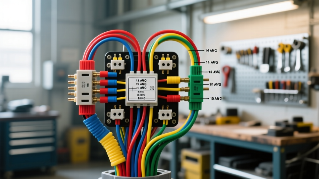
The Hidden Dangers of Incorrect Automotive Wire Gauge Sizing
When modifying or repairing a vehicle's electrical system, selecting the correct automotive wire gauge is often treated as a secondary concern. Many DIY enthusiasts and even some junior technicians rely on basic ampacity charts that only indicate the threshold at which a wire will melt. However, in modern vehicles packed with sensitive ECUs, CAN-bus networks, and high-draw fuel systems, a wire that does not melt can still cause catastrophic failures through severe voltage drop, brownouts, and localized heat buildup. Understanding the physics of DC current flow, temperature derating, and material composition is essential to prevent electrical fires and intermittent drivability issues.
Mistake #1: Sizing for Ampacity Instead of Voltage Drop
The most pervasive error in automotive wiring is sizing a wire based solely on its maximum amperage rating. Ampacity charts tell you what current a wire can carry before the insulation melts or the copper core fuses. They do not tell you if the wire will deliver adequate voltage to the component at the end of the circuit.
For example, a standard 14 AWG copper wire can safely carry 15 amps continuously in a chassis wiring application without melting. However, if you run 15 feet of 14 AWG wire (30 feet total round-trip including the ground path) to a high-pressure fuel pump drawing 15 amps, the resistance of the wire will cause a voltage drop of approximately 1.1 volts. If your alternator is outputting 14.2V, the fuel pump only receives 13.1V. Modern brushless fuel pumps and sensitive ECU sensors require a strict 3% maximum voltage drop (less than 0.4V on a 14V system) to operate within factory tolerances. Undersizing the wire forces the fuel pump to draw more current to compensate for the lower voltage, creating a thermal runaway loop that eventually melts the connector pins.
Mistake #2: Using CCA (Copper Clad Aluminum) in High-Vibration Environments
To cut costs, many budget wiring kits use Copper Clad Aluminum (CCA) wire. CCA wire features an aluminum core with a thin copper plating. While it looks like pure copper at the termination points, aluminum has only about 61% of the conductivity of pure copper. Consequently, a 10 AWG CCA wire performs electrically like a 12 AWG or even 14 AWG pure copper wire. Furthermore, aluminum is highly susceptible to work-hardening and fatigue cracking under the constant vibration of a vehicle chassis. The SAE J1128 standard for automotive primary wire strictly mandates pure copper conductors to ensure strand flexibility and consistent conductivity over thousands of miles of vibration.
Mistake #3: Ignoring Temperature Derating in the Engine Bay
Wire gauge ampacity is typically rated at an ambient temperature of 20°C (68°F). Under-hood temperatures near exhaust manifolds, turbochargers, or cylinder heads can easily exceed 100°C (212°F). As ambient temperature rises, the electrical resistance of the copper increases, and the insulation's thermal threshold is pushed closer to its limit.
If you are routing a 12 AWG GPT (General Purpose Thermoplastic) wire through an engine bay where ambient temperatures reach 85°C, you must apply a temperature derating factor of roughly 0.88. This means your 12 AWG wire is now only safe for 88% of its standard chassis ampacity. For high-temperature zones, you must upgrade to Cross-Linked polyethylene wire (GXL or TXL), which features thinner insulation but higher thermal resistance (up to 125°C), and physically upsize the wire gauge by one or two steps to compensate for the heat.
Mistake #4: Fusing the Load Instead of the Wire
A critical safety warning regarding automotive wire gauge involves fuse placement and sizing. A fuse is designed to protect the wire, not the component. If you install a 10 AWG wire capable of handling 30 amps, but the aftermarket LED light bar you are powering only draws 10 amps, you might be tempted to install a 15-amp fuse. While this protects the light bar, it leaves the wire under-protected in the event of a dead short to the chassis. The correct protocol is to size the wire gauge to handle the maximum possible fault current before the fuse blows, ensuring the wire never becomes the fuse. Always place the fuse within 18 inches of the battery positive terminal to protect the entire length of the harness.
Technical Reference: 12V Automotive Voltage Drop & Resistance Chart
The following table provides pure copper resistance data and maximum one-way run lengths for a 12V automotive system, targeting a strict 2% voltage drop (0.28V drop on a 14V charging system) to ensure ECU and sensor reliability. Data aligns with standard voltage drop calculation methodologies used in professional automotive electrical engineering.
| AWG Gauge | Resistance per 1,000 ft (Ω) | Max Chassis Amps (Pure Copper) | Max Length @ 10A (2% Drop) | Max Length @ 20A (2% Drop) |
|---|---|---|---|---|
| 18 AWG | 6.385 Ω | 10 A | 2.2 ft | Not Recommended |
| 16 AWG | 4.016 Ω | 13 A | 3.5 ft | 1.7 ft |
| 14 AWG | 2.525 Ω | 15 A | 5.5 ft | 2.8 ft |
| 12 AWG | 1.588 Ω | 20 A | 8.8 ft | 4.4 ft |
| 10 AWG | 0.999 Ω | 30 A | 14.0 ft | 7.0 ft |
| 8 AWG | 0.628 Ω | 40 A | 22.3 ft | 11.1 ft |
Note: Max Length represents the one-way distance from the power source to the load. The total circuit length (round-trip) is double this value.
Real-World Failure Mode: The Fuel Pump Driver Module (FPDM) Meltdown
A textbook example of automotive wire gauge failure is found in the 2005-2014 Ford Mustang GT platform. The factory Fuel Pump Driver Module (FPDM) is mounted in the trunk area and controls the high-pressure fuel pump. The factory ground wire for the FPDM is a 14 AWG black wire terminating in a standard ring terminal to the chassis.
The Failure: When owners upgrade to higher-flowing fuel pumps for forced induction applications, the continuous current draw spikes from the factory 12A to over 18A. The 14 AWG ground wire, already subjected to minor voltage drops, begins to overheat. The heat transfers directly into the Metri-Pack 280 connector pins, causing the plastic housing to warp and the female terminal to lose its spring tension. This increases resistance, generating more heat in a destructive feedback loop until the ground wire melts completely, killing the engine under heavy load.
The Fix: The correct repair is not just replacing the melted connector. You must upgrade the ground path to a 10 AWG pure copper wire (SAE black insulation). The chassis ground point must be stripped to bare metal, treated with a dielectric grease to prevent galvanic corrosion, and secured with an M8 bolt torqued to exactly 15 Nm using a star washer to bite through any residual paint. Finally, the connector pins must be upgraded to heavy-duty, silver-plated terminals with proper weather-pack silicone seals to block moisture ingress.
Proper Chassis Grounding Protocols
The ground return path is just as critical as the positive feed. A common mistake is using a smaller gauge wire for the ground, assuming the vehicle's steel chassis will handle the return current. While the chassis is part of the circuit, localized ground wires must match or exceed the positive wire gauge. When terminating ground wires, always use closed-end, heat-shrink ring terminals. Open-end "fork" terminals can slip under vibration, creating an immediate high-resistance arc fault. For high-amperage grounds (such as engine block to chassis straps), use 4 AWG or 2 AWG flexible braided copper straps, as solid stranded wire can suffer from strand-by-strand fatigue failure near the crimp barrel over years of engine torque roll.
Summary of Best Practices
- Always calculate voltage drop, not just ampacity, especially for EFI sensors and CAN-bus lines.
- Reject CCA wire; insist on 99.9% pure oxygen-free copper (OFC) meeting SAE J1128.
- Derate for heat by upsizing the gauge when routing through firewall grommets or near exhaust components.
- Protect the wire with appropriately sized fuses placed within 18 inches of the power source.
- Use proper tooling: Ratcheting crimpers calibrated for the specific terminal series (e.g., Delphi Weather-Pack or Deutsch DT) are mandatory for gas-tight, millivolt-drop connections.
For further reading on 12V DC circuit protection and wire sizing, the Blue Sea Systems Circuit Wizard provides excellent cross-referencing tools for marine and high-performance automotive applications, bridging the gap between basic DIY charts and professional engineering standards.