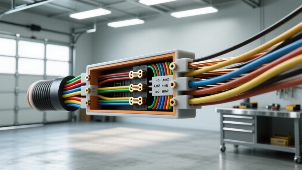
The Metric vs. Imperial Headache in Custom Automotive Wiring
When fabricating custom harnesses for EV swaps, classic car restomods, or high-output audio systems, sourcing high-strand-count flexible wire often leads you to European metric cable. Metric wire, measured in square millimeters (mm²), offers superior flexibility (Class 5 and 6 stranding) compared to standard US AWG wire. This extreme flexibility makes routing through tight firewall grommets and complex engine bays significantly easier. However, substituting metric wire into an SAE-designed vehicle requires a precise wire gauge conversion table to prevent dangerous bottlenecks, excessive voltage drop, and terminal mismatch.
Automotive modifiers frequently assume that a 4 AWG wire is exactly equal to a 25mm² cable. This is a dangerous misconception that can lead to undersized conductors in high-amperage circuits. According to the SAE J1128 Standard for Low Tension Primary Cable, American wire sizes are based on circular mils, while the ISO 6722 and DIN 72551 standards base metric sizes on exact cross-sectional copper area. Below is the definitive reference guide for translating these measurements during your next upgrade project.
Comprehensive Wire Gauge Conversion Table (AWG to mm²)
The following table maps standard American Wire Gauge (AWG) sizes to their closest metric (mm²) equivalents. Note the 'Actual Area' column, which reveals the true copper cross-section of the AWG size. Always round up in cross-sectional area when substituting metric wire for high-amperage chassis wiring to maintain equivalent or better ampacity.
| AWG Size | Metric Nominal (mm²) | Actual AWG Area (mm²) | Max Ampacity (Chassis 105°C) | Resistance (Ω/1000ft) |
|---|---|---|---|---|
| 18 AWG | 0.75 mm² | 0.823 mm² | 16 Amps | 6.385 |
| 16 AWG | 1.0 mm² | 1.309 mm² | 22 Amps | 4.016 |
| 14 AWG | 1.5 mm² | 2.082 mm² | 32 Amps | 2.525 |
| 12 AWG | 2.5 mm² | 3.309 mm² | 41 Amps | 1.588 |
| 10 AWG | 4.0 mm² | 5.261 mm² | 57 Amps | 0.9989 |
| 8 AWG | 6.0 mm² | 8.366 mm² | 73 Amps | 0.6282 |
| 4 AWG | 25 mm² | 21.15 mm² | 130 Amps | 0.2485 |
| 2 AWG | 35 mm² | 33.63 mm² | 150 Amps | 0.1563 |
| 1/0 AWG | 50 mm² | 53.48 mm² | 170 Amps | 0.0983 |
| 2/0 AWG | 70 mm² | 67.43 mm² | 195 Amps | 0.0779 |
Note: Ampacity ratings are based on single conductors in free air at 105°C ambient, referencing Pacer Group Marine and Automotive Ampacity Charts. Bundled harnesses require a 20-30% derating factor.
Real-World Mod: The Big 3 Upgrade Using Metric Cable
The 'Big 3' upgrade is a staple modification for vehicles running high-output alternators (200A+), winches, or massive audio amplifiers. The three circuits upgraded are:
- Alternator Positive to Battery Positive
- Engine Block to Chassis Ground
- Battery Negative to Chassis Ground
Many modifiers opt for 50mm² metric welding cable instead of 1/0 AWG because the Class 6 ultra-fine stranding makes it vastly easier to bend around tight LS-swap engine mounts. However, looking at the wire gauge conversion table above, 1/0 AWG is actually 53.48mm². By using 50mm² metric wire, you are technically dropping 3.48mm² of copper cross-section.
Calculating Voltage Drop in Mixed-Gauge Harnesses
Is this 6.5% reduction in copper acceptable? For a standard 3-foot run from the alternator to the battery, the voltage drop difference is negligible (less than 0.05V at 200 Amps). However, if you are routing a ground cable from a rear-mounted battery in a trunk to a front-mounted engine block (exceeding 12 feet total loop length), 50mm² will result in a voltage drop exceeding 0.3V under heavy load. In long-run scenarios, you must step up to 70mm² metric cable to match or exceed the performance of 1/0 AWG.
Terminal and Connector Compatibility (Metric vs SAE)
The most common point of failure in mixed-gauge harness builds is terminal mismatch. Metric wire requires metric lugs. Because metric wire utilizes finer stranding (as detailed by Madsen Enterprises Wire Stranding Classifications), the overall outer diameter (OD) of a 35mm² cable is often slightly larger than a 2 AWG cable due to the air gaps between the micro-strands.
If you attempt to crimp a standard US 3/8-inch ring terminal onto a 35mm² metric wire, the barrel will be loose. This creates high electrical resistance, leading to localized heat melting and potential fire.
Metric Lug Sizing Matrix
- 16mm² Wire: Requires M6 (6mm / approx 1/4') Ring Terminal
- 25mm² Wire: Requires M8 (8mm / approx 5/16') Ring Terminal
- 35mm² Wire: Requires M10 (10mm / approx 3/8') Ring Terminal
- 50mm² Wire: Requires M10 or M12 (10mm-12mm / 3/8'-1/2') Ring Terminal
Always verify the stud size on your alternator output post and chassis grounding busbar before ordering terminals. Many modern high-amp alternators use an M8 stud, meaning you must use an M8 ring terminal, even if you are running massive 50mm² cable. In this case, use a reducing pin or a custom-machined terminal to ensure the wire barrel matches the 50mm² wire while the ring eye fits the M8 stud.
Cross-Referencing OEM Color Codes (DIN vs SAE)
When integrating new metric wire into an existing factory harness, color coding becomes a major hurdle. The US relies on SAE J1128 color standards, while European vehicles and metric wire manufacturers follow DIN 72551 or ISO 6722.
- Ground Circuits: SAE typically uses solid Black or Black with a tracer. DIN standardizes on solid Brown (Braun) for ground. When splicing metric ground wire into a US harness, use heat-shrink butt connectors with clear transitions so future mechanics understand the color swap.
- Ignition/Switched 12V: SAE often uses Pink or Purple. DIN frequently uses Black/White or Black/Yellow tracer combinations.
- Constant 12V Battery: SAE uses Red or Orange. DIN typically uses solid Red or Red/White.
Always label both ends of any custom harness run with printed heat-shrink tubing detailing the circuit function and the AWG/mm² equivalent, rather than relying solely on insulation color.
Troubleshooting Mixed-Gauge Crimp Failures
When working with a wire gauge conversion table to swap between AWG and mm², crimping tools must be adjusted. Here is a diagnostic matrix for common failures:
Symptom: Terminal barrel pulls out under mild tension
Cause: Using an AWG closed-barrel hex die on mm² Class 5/6 wire. Metric wire has a larger overall diameter due to finer stranding. The AWG die crushes the outer strands but fails to compress the core.
Fix: Use a four-indent hex crimp die specifically sized for the mm² cross-section (e.g., a 25mm² die, not a 4 AWG die), or switch to an open-barrel F-crimp terminal which adapts better to varying wire ODs.
Symptom: Ring terminal stud hole does not fit chassis bolt
Cause: Sourced US 3/8-inch lugs for 35mm² metric wire. 3/8-inch is 9.52mm, which will bind on an M10 (10mm) bolt, stripping the threads or failing to seat flush against the busbar, creating a high-resistance ground.
Fix: Source true DIN metric lugs (M10) for 35mm² wire. If forced to use SAE lugs, carefully file the inside of the ring eye, but never stretch the copper ring with a screwdriver, as this work-hardens and weakens the terminal.
Final Verification Steps
Before applying power to any custom harness utilizing converted metric wire, perform a millivolt drop test across every crimped joint under maximum load. A properly crimped metric-to-AWG transition should show less than 10mV (0.010V) of drop across the terminal. By respecting the exact cross-sectional areas outlined in the wire gauge conversion table and matching your terminals to the metric standard, your upgrade project will deliver reliable, high-amperage performance for years to come.