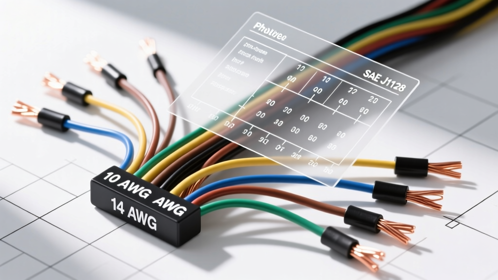
The Mathematics of AWG: Calculating Wire Gauge to Inch
When engineering custom automotive wiring harnesses or upgrading high-current charging systems, understanding the exact physical dimensions of your conductors is non-negotiable. The American Wire Gauge (AWG) system is a standardized, logarithmic wire sizing standard used predominantly in North America. However, AWG numbers themselves are abstract; to physically route wires through bulkheads, select proper Deutsch connectors, or calculate conduit fill ratios, you must perform a wire gauge to inch conversion.
The AWG system operates on a reverse logarithmic scale: the smaller the gauge number, the larger the wire diameter. The mathematical formula to convert any AWG size to its bare copper diameter in inches is:
Diameter (inches) = 0.005 × 92^((36 - AWG) / 39)
Because of this geometric progression, dropping exactly three AWG sizes (e.g., from 10 AWG to 7 AWG) doubles the cross-sectional area of the wire and halves its electrical resistance. Dropping six sizes doubles the diameter. This mathematical predictability is what allows automotive electrical engineers to precisely calculate voltage drop over long harness runs, such as the 15-foot routing from a front-mounted alternator to a trunk-mounted battery in a pro-touring build.
Comprehensive Wire Gauge to Inch Conversion Table
The table below provides the critical wire gauge to inch conversions required for automotive applications, alongside metric equivalents and SAE ampacity ratings. Note that ampacity ratings vary based on insulation type and ambient under-hood temperatures.
| AWG Size | Bare Diameter (Inches) | Bare Diameter (mm) | Area (Circular Mils) | SAE J1128 Ampacity (125°C) |
|---|---|---|---|---|
| 4/0 | 0.4600 | 11.684 | 211,600 | 275A |
| 2/0 | 0.3648 | 9.266 | 133,100 | 215A |
| 1/0 | 0.3249 | 8.252 | 105,600 | 185A |
| 2 | 0.2576 | 6.543 | 66,360 | 150A |
| 4 | 0.2043 | 5.189 | 41,740 | 120A |
| 6 | 0.1620 | 4.115 | 26,240 | 95A |
| 8 | 0.1285 | 3.264 | 16,510 | 75A |
| 10 | 0.1019 | 2.588 | 10,380 | 55A |
| 12 | 0.0808 | 2.052 | 6,530 | 40A |
| 14 | 0.0641 | 1.628 | 4,110 | 30A |
| 16 | 0.0508 | 1.290 | 2,580 | 22A |
| 18 | 0.0403 | 1.024 | 1,620 | 16A |
| 20 | 0.0320 | 0.813 | 1,020 | 11A |
| 22 | 0.0253 | 0.643 | 640 | 8A |
Data derived from standard AWG mathematical models and cross-referenced with the Copper Development Association Wire Table.
SAE J1128 vs. Standard AWG: The Insulation Factor
A common pitfall for novice harness builders is assuming the bare copper wire gauge to inch measurement dictates the physical space the wire will occupy. In automotive environments, bare wire is never used; it must be insulated against heat, moisture, and abrasion. The SAE International J1128 standard governs low-tension primary cable used in surface vehicles.
Under SAE J1128, insulation thickness adds significantly to the overall Outer Diameter (OD). For example:
- 10 AWG Bare: 0.1019 inches
- 10 AWG SAE HDT (High-Temp Thermoplastic): ~0.145 inches OD
- 10 AWG SAE SXL (Cross-Linked Polyethylene): ~0.135 inches OD
SXL insulation is thinner but offers superior heat resistance (up to 125°C continuous, 150°C peak) compared to standard PVC. When routing 10 AWG SXL wire through a firewall grommet, you must use the 0.135-inch OD for your fill-ratio calculations, not the 0.1019-inch bare copper diameter. For extreme environments, such as turbocharger proximity, PTFE (Teflon) insulated wire like Belden's automotive high-temp lines may be required, which alters the OD slightly due to the extrusion process of the fluoropolymer.
Practical Applications: Sizing Auto Harnesses by Inch Diameter
High-Current Circuits: Starter, Alternator, and EV Battery
When upgrading a classic muscle car to a modern 140A+ alternator, the factory 10 AWG charge wire will melt. Upgrading to 4 AWG wire (0.2043 inches bare, ~0.26 inches OD) is standard practice. At the battery terminal, utilizing a 4/0 AWG (0.4600 inches) copper lug for the main ground strap requires precise torque. A 3/8-inch stud on a heavy-duty battery terminal lug torqued to 12-15 ft-lbs ensures the massive cross-sectional area (211,600 circular mils) maintains low millivolt drop during the 400+ amp draw of a starter motor cranking a high-compression V8.
CAN Bus and Sensor Networks: 18 AWG to 22 AWG
Modern engine management relies on high-speed data. GM's Gen V LT1 CAN bus networks utilize twisted pair wiring, typically 22 AWG (0.0253 inches bare). The specific colors for the GM High-Speed GMLAN are often Gray/Black (CAN High) and Green/Black (CAN Low). Because 22 AWG is physically fragile, it is rarely crimped directly into standard spade terminals. Instead, it is pinned into high-density connectors like the TE Superseal 1.5 or Molex MX150 series. The MX150 terminal cavity is engineered specifically to accept the OD of 14 through 22 AWG insulated wire, relying on the precise silicone mat seal to prevent moisture ingress based on the wire's exact outer diameter.
Harness Routing, Grommets, and Fill Ratios
When passing a multi-wire harness through a vehicle's firewall or a metal bulkhead, calculating the fill ratio is critical to prevent chafing and short circuits. The National Electrical Code (NEC) recommends a maximum 40% fill ratio for conduits, a principle that translates directly to automotive rubber grommets.
To calculate this, convert your wire gauge to inch OD, find the cross-sectional area of each wire (Area = π × r²), sum them, and divide by the inner area of the grommet. If you are routing four 12 AWG wires (OD 0.120 inches) and six 18 AWG wires (OD 0.085 inches), the total wire area is roughly 0.079 square inches. You must select a bulkhead grommet with an internal diameter of at least 0.55 inches to maintain a safe 40% fill ratio, allowing the rubber to compress and seal without crushing the SXL insulation against the sharp edges of the firewall knockout.