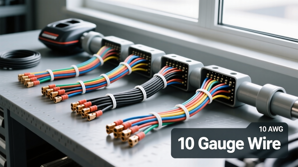
Is 10 AWG the Right Choice for Your Trolling Motor?
When wiring a 12V auxiliary system, selecting the correct conductor is critical for performance and safety. Using 10 gauge wire for trolling motor applications is a popular choice for smaller 12-voltage setups, typically those drawing under 40 amps (such as 30 lb to 45 lb thrust models). However, the marine and automotive environments are incredibly hostile to electrical systems. Saltwater, bilge water, vibration, and UV exposure demand a rigorous approach to material selection and termination.
Before purchasing a spool of wire, installers must evaluate the true cost of ownership—which extends far beyond the price per foot of the copper itself. This guide breaks down the electrical physics, material cost analysis, and specialized tooling required to execute a professional-grade 10 AWG trolling motor installation that complies with both ABYC (American Boat & Yacht Council) and SAE (Society of Automotive Engineers) standards.
The Physics of 10 AWG: Ampacity vs. Voltage Drop
A common mistake in automotive and marine wiring is sizing wire solely based on its thermal ampacity (the point at which the insulation melts). According to the ABYC E-11 standard, 10 AWG copper wire with 105°C insulation can safely carry up to 45 amps in a non-engine space environment. However, thermal limits are irrelevant if your trolling motor starves from voltage drop.
Voltage drop is the resistance encountered over the total length of the circuit (positive and negative runs combined). A 12V trolling motor requires a minimum of 11.5V at the terminals to operate efficiently. If voltage drops below this threshold, the motor will draw more current to compensate for the lost power, leading to overheated windings and tripped breakers.
10 AWG Voltage Drop Reference Chart (12V System)
| Total Wire Run (Pos + Neg) | Max Current (3% Drop Limit) | Max Current (10% Drop Limit) | Typical Trolling Motor Application |
|---|---|---|---|
| 10 Feet | 38 Amps | 125 Amps | 30 lb thrust (Max draw ~30A) |
| 15 Feet | 25 Amps | 83 Amps | Underpowered for most motors |
| 20 Feet | 19 Amps | 62 Amps | Requires upgrade to 8 AWG or 6 AWG |
Expert Rule of Thumb: 10 AWG is only acceptable for 10 gauge wire for trolling motor setups if the total round-trip wire distance is under 12 feet and the motor's maximum amperage draw does not exceed 35 amps. For 24V or 36V systems, current draw is halved or thirded, making 10 AWG viable for much longer runs.
Material Cost Breakdown: Marine Tinned vs. Automotive Bare
The most critical cost decision you will make is choosing between standard automotive wire (SAE J1128) and marine-grade tinned wire (UL 1426). While bare copper automotive wire is significantly cheaper upfront, it will succumb to galvanic corrosion and 'black wire syndrome' within a single season if exposed to moisture.
Component Cost Analysis (Per 20-Foot Installation)
| Component | Automotive Grade (Bare Copper) | Marine Grade (Tinned Copper) | Longevity & Performance Impact |
|---|---|---|---|
| 10 AWG Wire (20 ft) | $12.00 - $16.00 | $30.00 - $45.00 | Tinned strands resist capillary corrosion. |
| Ring Terminals (Qty 4) | $2.50 (Vinyl Insulated) | $6.00 (Tinned Copper, Uninsulated) | Uninsulated allows for proper heat shrink sealing. |
| Adhesive Heat Shrink | $0.00 (Usually omitted) | $12.00 (3:1 Marine Grade) | Melts adhesive to block moisture ingress. |
| Inline Circuit Breaker | $15.00 (Standard Auto) | $35.00 (Marine IP67 Rated) | Ignition protected and corrosion resistant. |
| Total Estimated Cost | ~$29.50 | ~$83.00 | Marine setup lasts 10x longer in wet environments. |
While the marine-grade setup costs nearly three times as much, the cost of replacing a corroded wiring harness or diagnosing a dead trolling motor on the water far outweighs the initial $50 savings. For any vessel that leaves the dry garage, marine-grade tinned 10 AWG is a non-negotiable requirement.
Essential Tooling for 10 AWG Marine Connections
You cannot achieve a reliable, high-amperage connection using cheap, non-ratcheting pliers. 10 AWG stranded wire (which typically consists of 105 individual 30 AWG strands for flexibility) requires immense mechanical pressure to cold-weld the copper strands to the terminal barrel. If the crimp is loose, resistance increases, generating heat that can melt the terminal and start a fire.
Required Tool List
- Ratcheting Crimper (AWG 10-8): Tools like the IWISS IWS-16 or Titan 11110 ensure a consistent, hex-indent crimp every time. The ratchet mechanism prevents the tool from releasing until the exact required pressure is achieved.
- Precision Wire Strippers: Standard pliers will nick the 30 AWG micro-strands, reducing the wire's cross-sectional area and creating a weak point. Use a dedicated 10-8 AWG wire stripper to cleanly remove exactly 5/16' of insulation.
- Marine Heat Shrink (3:1 or 4:1 Ratio): Standard 2:1 electrical heat shrink is useless in marine environments. You must use dual-wall, adhesive-lined heat shrink. When heated, the inner wall melts and flows into the wire strands, creating a 100% waterproof seal.
- Heat Gun (Not a Lighter): A focused heat gun with a reflector nozzle ensures the adhesive shrink seals evenly without scorching the insulation.
- Torque Wrench (Inch-Pounds): Terminals on trolling motor quick-disconnects and busbars must be torqued to spec (usually 35-50 in-lbs for 1/4' studs) to prevent vibration loosening.
Step-by-Step Termination & Routing Protocol
Executing the termination properly is where the investment in your tools pays off. Follow this sequence for every 10 AWG connection:
- Strip and Inspect: Strip 5/16' of insulation. Inspect the tinned strands to ensure none were cut or frayed during stripping.
- Insert and Seat: Slide a piece of 1/2' adhesive-lined heat shrink onto the wire before crimping. Insert the bare copper fully into the uninsulated tinned terminal barrel. You should see a tiny 'mouse tail' of wire protruding from the front of the barrel to confirm full insertion.
- Ratchet Crimp: Place the terminal in the correct die of your ratcheting crimper (usually marked for 10 AWG or yellow-coded sizes). Squeeze until the ratchet clicks and releases.
- Shrink and Seal: Slide the heat shrink so it covers half the terminal barrel and half the wire insulation. Apply heat from the middle outward, pushing the melted adhesive out of both ends slightly. This visual 'ooze' is your guarantee of a waterproof seal.
- Route and Protect: Route the positive (Red) and negative (Yellow or Black, per ABYC E-11 DC standards) wires together. Secure them every 18 inches using UV-resistant cable clamps. Keep the wires away from sharp aluminum hull edges and moving steering cables.
Hardware & Circuit Protection
The Blue Sea Systems circuit protection guidelines dictate that overcurrent protection must be installed within 7 inches of the power source (the battery positive terminal). For a 10 AWG wire run powering a 35-amp trolling motor, a 40-Amp or 50-Amp manual reset marine circuit breaker is required.
Do not use standard automotive blade fuses for trolling motors. Trolling motors experience massive 'inrush' currents when starting or when the prop snags on weeds. A standard glass AGU or blade fuse will suffer from metal fatigue and nuisance-trip under these surge conditions. A thermal-magnetic marine breaker handles these micro-second surges while still protecting the 10 AWG wire from a dead short.
Real-World Failure Modes & Troubleshooting
Even with 10 gauge wire for trolling motor setups, failures occur when installation shortcuts are taken. Here are the most common field failures:
- Capillary Corrosion (Black Wire Syndrome): Caused by using bare copper wire or failing to seal the terminal with adhesive heat shrink. Moisture wicks up inside the wire insulation via capillary action, turning the copper black and resistive all the way back to the battery. Fix: Cut back the wire until bright copper is found, or replace the entire run with tinned marine wire.
- Voltage Drop Under Load: The motor runs fine out of the water but bogs down and clicks off when placed under the load of moving the boat. Fix: Measure voltage at the motor terminals while under load. If it drops below 11.5V, the 10 AWG wire is too thin for the distance. Upgrade to 8 AWG or 6 AWG.
- Thermal Terminal Failure: The heat shrink is melted or discolored near the crimp barrel. This indicates a high-resistance connection caused by a poor crimp or undersized terminal stud hole. Fix: Cut off the terminal, re-crimp with a calibrated ratcheting tool, and ensure the terminal hole perfectly matches the busbar stud size without forcing it.
By investing in the correct marine-grade materials and precision tooling, your 10 AWG trolling motor installation will provide years of reliable, voltage-stable performance, regardless of the aquatic environment.