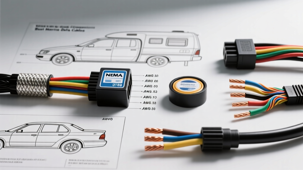
Understanding NMEA 0183 Electrical Requirements
When integrating GPS receivers, sonars, autopilots, and multiplexers in marine and expedition RV environments, the physical layer of your data network is just as critical as the software configuration. The NMEA 0183 protocol relies on RS-422 differential signaling (or occasionally RS-232 for legacy single-ended PC connections). Because RS-422 transmits data using a balanced voltage differential across a twisted pair, it is highly resistant to common-mode noise. However, selecting the correct NMEA 0183 wire gauge and shielding topology is mandatory to prevent signal degradation, especially when routing cables near high-amperage alternators, inverters, and ignition systems.
Unlike high-current automotive power feeds where ampacity dictates the American Wire Gauge (AWG), NMEA 0183 data lines carry negligible current (typically under 50mA). Therefore, the primary considerations for NMEA 0183 wire gauge are capacitance, impedance, and physical tensile strength rather than current-carrying capacity. According to the National Marine Electronics Association (NMEA), standard baud rates of 4800 bps and High-Speed (HS) rates of 38400 bps require cabling that maintains signal integrity over runs that can exceed 50 feet in large vessels or Class A motorhomes.
The Critical Role of Wire Gauge and Shielding
For the data pairs (Talker A/B and Listener A/B), 22 AWG is the industry standard for RS-422 networks. It provides the optimal balance of low inter-wire capacitance and flexibility. However, in harsh marine and off-grid RV environments, 22 AWG can be too fragile for pulling through tight conduits or terminating into ruggedized Deutsch DT connectors. In these applications, stepping up to 18 AWG or 20 AWG shielded twisted pair (STP) is highly recommended for physical durability, provided the cable maintains a characteristic impedance close to 120 ohms.
For the power feeds to the NMEA 0183 devices, gauge selection reverts to standard voltage drop calculations. A typical GPS sensor draws less than 150mA, but a dedicated NMEA multiplexer or a legacy chartplotter may draw 1.5A to 3A. Following ABYC E-11 standards for marine and RV DC systems, a 16 AWG marine-grade tinned copper wire is generally sufficient for power runs up to 15 feet, while 14 AWG should be used for longer runs to prevent voltage drop below the device's 10.5V minimum operating threshold.
Product Comparison: Top Shielded Cables for NMEA 0183
Choosing the right cable involves balancing electrical specifications with environmental durability. Below is a comparison of the top cable types used by professional marine electricians and RV integrators for NMEA 0183 wire gauge applications.
| Cable Type | AWG Size | Shielding & Impedance | Best Application | Pros & Cons |
|---|---|---|---|---|
| Belden 9842 | 22 AWG | Overall Braid, 120Ω Impedance | Long RS-422 runs, Multiplexers, PC interfaces | Pros: Exact RS-422 spec, low capacitance. Cons: Untinned copper, jacket degrades in UV/salt. |
| Ancor Marine Shielded | 18 AWG | Foil + Drain Wire, Marine Grade | Masthead wiring, engine room routing, exterior sensors | Pros: Tinned copper, highly flexible, UV/salt resistant. Cons: Higher capacitance, impedance not strictly 120Ω. |
| Actisense NMEA 0183 OEM | 24 AWG | Pre-molded STP, IP67 Rated | Plug-and-play sensor drops, sealed enclosures | Pros: Factory sealed, guaranteed pinouts, waterproof. Cons: Fixed lengths, 24 AWG is fragile if extended. |
Selection Verdict
If you are wiring a new expedition truck or yacht from scratch and pulling cables through conduit, Ancor 18 AWG Shielded is the superior choice for physical resilience and corrosion resistance, despite its slightly higher capacitance. For complex data hubs, ShipModul MiniPlex installations, or runs exceeding 40 feet where signal reflection becomes an issue, Belden 9842 (22 AWG) is the undisputed champion due to its strict 120-ohm impedance matching.
NMEA 0183 Pinout and Wiring Configurations
One of the most common failure modes in NMEA 0183 networks is reversed polarity on the differential pairs. Unlike NMEA 2000, which uses a standardized CAN-bus trunk, NMEA 0183 is point-to-point. Below is the standard IEC 61162-1 color code and pinout reference for bare-wire and DB9 multiplexer connections.
| Function | Standard Wire Color | Signal Type | DB9 Pin (PC/Multiplexer) |
|---|---|---|---|
| Talker Data A (+) | White | RS-422 TX+ | Pin 3 (TXD) |
| Talker Data B (-) | Green | RS-422 TX- | Pin 8 (RTS / TX-) |
| Listener Data A (+) | Yellow | RS-422 RX+ | Pin 2 (RXD) |
| Listener Data B (-) | Blue | RS-422 RX- | Pin 7 (CTS / RX-) |
| Power Positive (+) | Red | 12V/24V DC | N/A (Direct to Bus) |
| Power Negative (-) | Black | DC Ground | Pin 5 (Signal Ground) |
| Shield / Drain | Bare / Silver | EMI Shield | Chassis Ground |
Note: Always verify manufacturer-specific color codes. Some legacy Japanese sonar manufacturers swap the Green and Blue assignments. Always test with a multimeter set to DC voltage; the A (+) line should read approximately +2.5V relative to ground, while the B (-) line should read -2.5V when transmitting.
Installation Rules: The Shield Grounding Mandate
The most critical aspect of installing any NMEA 0183 wire gauge configuration is managing the shield drain wire. Because marine and RV environments have multiple grounding points (engine block, chassis, hull, battery banks), ground potential differences are inevitable. If you ground the cable shield at both the Talker and the Listener, you create a ground loop. This loop will induce 60Hz alternator whine and low-frequency AC noise directly into your data lines, resulting in corrupted NMEA sentences (e.g., dropped GGA or RMC strings).
The Golden Rule of NMEA Shielding
- Ground the shield at the Talker (Transmitter) end ONLY.
- At the Listener (Receiver) end, cut the drain wire flush, fold it back over the cable jacket, and secure it with heat shrink to prevent accidental contact with the chassis or terminal block.
- Use opto-isolators on the Listener inputs whenever possible. High-quality multiplexers feature built-in optical isolation, which physically breaks the electrical connection while allowing light-based data transfer, completely eliminating ground loop risks.
Real-World Troubleshooting Matrix
When your chartplotter fails to receive AIS data or your autopilot loses its heading source, use this diagnostic matrix to isolate the physical layer fault.
| Symptom | Probable Cause | Diagnostic Test & Fix |
|---|---|---|
| Intermittent data loss when engine is running | EMI interference from alternator or unshielded ignition wires. | Verify STP cable is used. Ensure shield is grounded at one end. Reroute NMEA cables at least 12 inches away from high-current DC and AC lines. |
| Listener receives no data; Talker LED is flashing | Reversed A/B differential pairs or broken wire. | Swap the White/Green or Yellow/Blue pairs at the listener terminal. Check continuity with a multimeter; 22 AWG wire breaks easily inside insulation if pulled too hard. |
| Data works, but drops out when battery voltage fluctuates | Shared ground reference causing common-mode voltage exceedance. | RS-422 receivers can handle up to ±7V common-mode. If ground potential exceeds this, install an isolated DC-DC converter for the Talker's power feed. |
| Corrupted text / random characters in terminal | Baud rate mismatch or excessive cable capacitance. | Confirm both devices are set to 4800 or 38400 (HS). If using non-spec cable over 50ft, replace with 120Ω Belden 9842 to reduce signal smearing. |
Final Recommendations for RV and Marine Integrators
Do not compromise on the physical layer of your serial data networks. While it is tempting to use leftover 18 AWG automotive primary wire for NMEA 0183 data runs, the lack of twisting and shielding will inevitably lead to phantom data and frustrating diagnostic sessions. Invest in purpose-built RS-422 STP cabling, adhere strictly to the single-point shield grounding rule, and utilize marine-grade tinned connectors with dielectric grease to ensure your telemetry network survives the harsh realities of the road and the sea.