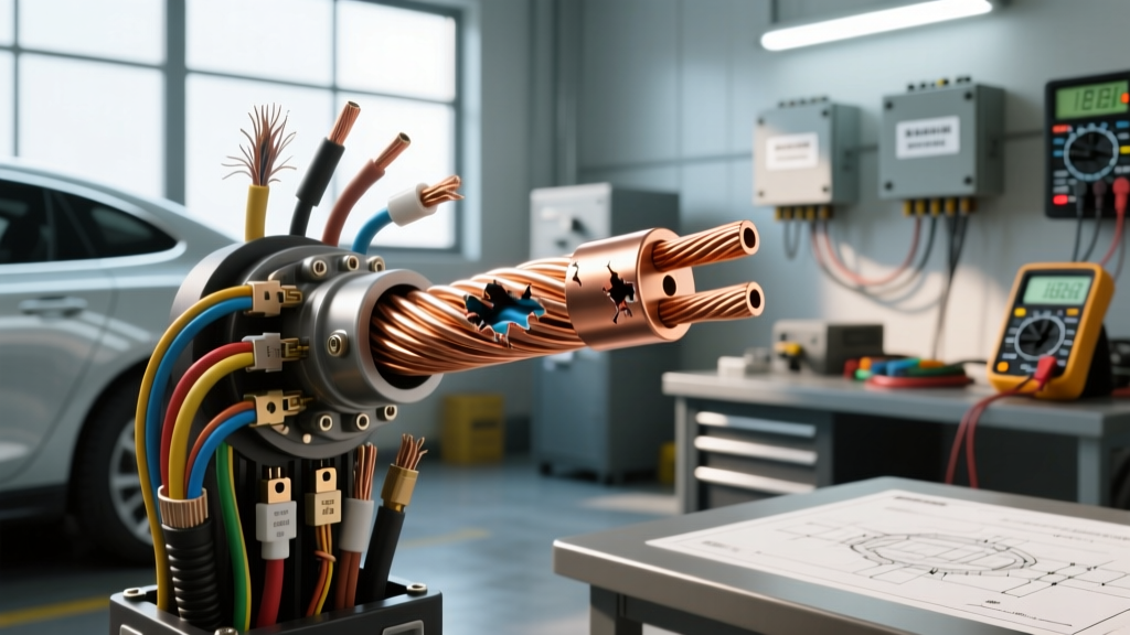
The Hidden Dangers of Misusing Eight Gauge Wire
When building custom automotive electrical systems, upgrading high-output alternators, or installing high-draw audio amplifiers, eight gauge wire is frequently the go-to conductor. Capable of handling substantial current, 8 AWG is a staple in the automotive electrician's toolkit. However, the margin for error with high-amperage circuits is razor-thin. Misunderstanding ampacity ratings, ignoring voltage drop over distance, or utilizing substandard wire materials can lead to catastrophic insulation melt, voltage starvation at critical components, and severe electrical fires.
This comprehensive guide explores the most critical safety warnings and common mistakes associated with eight gauge wire in automotive applications. By understanding the strict differences between wiring standards and mastering proper termination techniques, you can ensure your high-current circuits operate safely and efficiently under the harshest under-hood conditions.
Understanding True Ampacity: SAE vs. AWG Standards
One of the most dangerous mistakes an automotive technician can make is applying residential electrical codes to a vehicle. The National Electrical Code (NEC) and the Society of Automotive Engineers (SAE) rate wire ampacity very differently due to the operating environment.
Under the NFPA 70 NEC guidelines, 8 AWG copper wire in a free-air chassis wiring setup might be rated for up to 73 amps. However, automotive engine bays are high-temperature environments. The SAE J1128 standard accounts for elevated ambient temperatures (often exceeding 105°C to 125°C for GXL/TXL insulation) and wire bundling. When you bundle multiple 8 AWG wires together in a split-loom conduit behind the dashboard or route them near exhaust headers, the heat dissipation drops drastically. In a true automotive engine bay application, a conservative and safe continuous ampacity rating for 8 AWG is between 40 and 50 amps.
The Copper-Clad Aluminum (CCA) Trap
Perhaps the most pervasive safety hazard in aftermarket automotive wiring is the use of Copper-Clad Aluminum (CCA) wire disguised as pure copper. CCA wire features an aluminum core with a thin copper electroplated coating. Aluminum has roughly 61% of the conductivity of pure Oxygen-Free Copper (OFC). Consequently, an 8 AWG CCA wire exhibits approximately 40% more electrical resistance than an 8 AWG OFC wire. In practical terms, 8 AWG CCA performs electrically like 10 AWG OFC. Running a 45-amp amplifier or a winch solenoid control circuit with 8 AWG CCA wire will result in severe voltage drops, overheating, and potential melting of the PVC jacket. Always verify that your wire is stamped with 'OFC' or 'Pure Copper' and inspect the cross-section; if the center of the strands is silvery-white, it is CCA and must be replaced.
Voltage Drop and Distance Calculations
Eight gauge wire has a nominal resistance of approximately 0.641 ohms per 1,000 feet at 20°C. While this seems negligible, in a 12-volt DC automotive system, distance is the enemy of current flow. Voltage drop is calculated using the formula: VD = (2 × Length × Current × Resistance) / 1000.
Consider a custom battery relocation kit utilizing 8 AWG wire routed from the trunk to the engine bay (a 15-foot run, meaning 30 feet total for positive and ground). If the starter motor pulls 150 amps momentarily, or a continuous accessory pulls 40 amps:
- At 40 Amps Continuous: Voltage Drop = (2 × 15 × 40 × 0.641) / 1000 = 0.77 Volts.
- At 150 Amps Peak (Starter): Voltage Drop = (2 × 15 × 150 × 0.641) / 1000 = 2.88 Volts.
A nearly 3-volt drop during cranking will drop your system voltage below 9.5V, potentially causing ECU resets, fuel pump starvation, and no-start conditions. For high-draw starter circuits, 8 AWG is vastly undersized; you must step up to 1/0 or 2/0 AWG welding cable. Eight gauge wire should be reserved for 40A-50A continuous accessory circuits, such as electric cooling fans, fuel pumps, or audio amplifiers.
Technical Specifications & Ampacity Chart
Reference the following specifications when sourcing and planning your 8 AWG automotive wiring harnesses. These values assume standard SAE J1128 GXL/TXL cross-linked polyethylene insulation.
| Wire Specification | Conductor Material | Stranding (Approx) | Ohms/1000ft @ 20°C | Max Amps (Chassis/Cabin) | Max Amps (Engine Bay) |
|---|---|---|---|---|---|
| 8 AWG SAE (OFC) | Pure Copper (OFC) | 1666 x 30 AWG | 0.641 Ω | 50A - 55A | 40A - 45A |
| 8 AWG SAE (CCA) | Copper-Clad Aluminum | 1666 x 30 AWG | 0.900 Ω | 35A - 40A | 25A - 30A |
| 8 AWG Welding Cable | Pure Copper (Fine) | 2107 x 34 AWG | 0.620 Ω | 60A | 50A |
Proper Termination and Connector Selection
The most common point of failure in any high-current circuit is not the wire itself, but the termination. A poor crimp creates a high-resistance junction. According to Joule's first law (P = I²R), as current flows through this high-resistance joint, it generates massive amounts of heat, leading to the infamous 'green death' (copper oxidation) and eventual thermal runaway.
Crimping and Heat Shrink Protocols
For 8 AWG wire, standard plier-style crimpers are entirely inadequate. You must use a heavy-duty ratcheting hex-crimp or indent-crimp tool specifically sized for #8 terminals. Hex crimps deform the barrel evenly, ensuring maximum surface area contact between the copper strands and the terminal barrel.
Always use adhesive-lined, dual-wall heat shrink terminals (typically featuring a 3:1 shrink ratio). When heated, the inner polyamide adhesive layer melts and flows between the wire strands, creating a waterproof seal that prevents oxygen and moisture from causing galvanic corrosion. Standard PVC electrical tape is strictly prohibited for high-current terminations; the heat generated by the wire will melt the adhesive, causing the tape to unravel and expose the bare copper to the elements.
Torque Specifications for High-Current Lugs
When securing 8 AWG ring terminals to distribution blocks, bus bars, or battery posts, proper torque is critical. Under-torquing allows the terminal to vibrate loose, increasing resistance. Over-torquing can snap the terminal stud or strip the threads in soft aluminum distribution blocks.
- M8 Stud (8mm): 10 - 12 Nm (89 - 106 in-lbs)
- M10 Stud (10mm): 15 - 18 Nm (133 - 159 in-lbs)
- Standard 3/8" Lead-Acid Battery Post: 5 - 7 Nm (44 - 62 in-lbs)
Real-World Troubleshooting: Failure Modes
Use this decision tree to diagnose common issues related to eight gauge wire installations in custom automotive builds.
- Symptom: Amplifier clipping at high volume / Headlights dimming in time with bass hits.
Cause: Severe voltage drop due to undersized wire, excessive run length, or the use of CCA wire instead of OFC.
Fix: Measure voltage at the amplifier's B+ terminal during peak draw. If it drops below 11.5V, upgrade to a larger gauge (e.g., 4 AWG) or verify the wire is pure OFC. - Symptom: Melted insulation or discoloration localized within two inches of the ring terminal.
Cause: High-resistance crimp joint. The wire strands were likely not fully inserted into the terminal barrel before crimping, or an incorrect crimp die was used.
Fix: Cut the terminal off immediately. Strip back to clean, unoxidized copper. Use a calibrated hex-crimp tool and adhesive-lined heat shrink to re-terminate. - Symptom: Intermittent loss of power to an accessory (e.g., electric cooling fan failing to trigger).
Cause: 'Green Death' oxidation inside a non-sealed crimp, or a loose M8/M10 fastener that has vibrated out of spec due to missing lock washers.
Fix: Disassemble the connection. Clean the bus bar contact surface with a wire brush and electrical contact cleaner. Re-torque the fastener to the manufacturer's specification using a split-lock washer or a Nord-Lock washer.
Authoritative References
For further reading on automotive electrical standards and wire sizing, consult the following resources:
- SAE J1128 Standard: Low Tension Primary Cable - Society of Automotive Engineers (Guidelines for automotive wire insulation and temperature ratings).
- NFPA 70: National Electrical Code (NEC) - National Fire Protection Association (Baselines for conductor ampacity and thermal derating).
- Madsen's Auto Wire & Tech Resources - Industry-standard reference for automotive voltage drop calculations and OFC vs CCA identification.