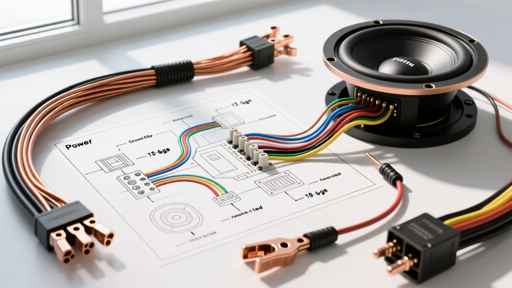
The Core Question: What Gauge Wire for Subs?
When designing a high-output car audio system, the most critical question installers face is, what gauge wire for subs is required to maintain signal integrity and system safety? Subwoofer amplifiers draw massive amounts of direct current (DC) from the vehicle's electrical system, and the speaker terminals push high-amperage alternating current (AC) to the voice coils. Undersizing your wire leads to severe voltage drop, amplifier clipping, thermal shutdown, and in extreme cases, electrical fires.
This complete wiring diagram walkthrough breaks down the four primary wire runs in a subwoofer installation: Main Power, Chassis Ground, Remote Turn-On, and Speaker Wire. We will evaluate exact American Wire Gauge (AWG) requirements based on the CTA-2015 Mobile Electronics Cables Standard and real-world automotive electrical constraints.
Stage 1: Battery to Amplifier (Main Power Wire)
The main power wire is the lifeline of your subwoofer system. It must deliver 12V to 14.4V DC from the battery (or front distribution block) to the amplifier's B+ terminal with minimal resistance. When determining what gauge wire for subs you need for the power run, you must calculate based on the total RMS wattage of the amplifier(s) and the total length of the wire run.
OFC vs. CCA: The Hidden Resistance Factor
Before selecting your AWG, you must identify the wire material. Oxygen-Free Copper (OFC) is the standard for automotive electrical systems. Copper-Clad Aluminum (CCA) is a cheaper alternative with approximately 40% higher electrical resistance. If you are forced to use CCA wire, you must step up one full gauge size (e.g., use 2 AWG CCA where 4 AWG OFC is specified) to compensate for the voltage drop. Always verify that your wire meets the SAE J1128 Low Tension Cable Standard for under-hood temperature and abrasion resistance.
Main Power AWG Reference Chart (OFC Wire)
| Total RMS Wattage | 0 - 4 Feet | 4 - 7 Feet | 7 - 10 Feet | 10 - 13 Feet | 13 - 16 Feet |
|---|---|---|---|---|---|
| 0 - 200W | 10 AWG | 8 AWG | 8 AWG | 6 AWG | 6 AWG |
| 200 - 400W | 8 AWG | 8 AWG | 6 AWG | 6 AWG | 4 AWG |
| 400 - 600W | 6 AWG | 6 AWG | 4 AWG | 4 AWG | 4 AWG |
| 600 - 1000W | 4 AWG | 4 AWG | 4 AWG | 2 AWG | 2 AWG |
| 1000 - 1500W | 2 AWG | 2 AWG | 1/0 AWG | 1/0 AWG | 1/0 AWG |
| 1500 - 2500W | 1/0 AWG | 1/0 AWG | 1/0 AWG | 2/0 AWG | 2/0 AWG |
Note: Wire length must be measured from the battery positive terminal to the amplifier, including the ground wire length back to the chassis.
Stage 2: Amplifier to Chassis (Ground Wire)
The ground wire completes the circuit. A fundamental rule of automotive electrical diagnostics is that the ground wire must be the exact same AWG and material as the main power wire. If you run 1/0 AWG power, you must run 1/0 AWG ground. Using a smaller ground wire creates a bottleneck, leading to voltage starvation at the amplifier's internal power supply.
Proper Grounding Procedure
According to Haynes Automotive Electrical Basics, chassis grounding requires bare metal-to-metal contact. Follow these steps to eliminate ground loop alternator whine and voltage drop:
- Location: Choose a factory-welded seam or a thick structural bolt directly to the chassis frame. Never ground to a seatbelt anchor, strut tower bolt, or thin sheet metal.
- Preparation: Use 80-grit sandpaper or a rotary wire brush to remove all paint, primer, and clear coat down to bare steel or aluminum.
- Termination: Use a high-quality, adhesive-lined heat shrink ring terminal. Crimp using a hex-crimp tool to ensure a gas-tight connection that resists vibration and moisture.
- Protection: After torquing the bolt (typically 15-20 ft-lbs for M8 bolts), coat the exposed bare metal with dielectric grease or battery terminal protector spray to prevent galvanic corrosion.
Stage 3: Head Unit to Amplifier (Remote Turn-On & Signal)
While power and ground handle the heavy lifting, the remote turn-on and signal wires dictate system control and audio fidelity.
Remote Turn-On Wire (REM)
The remote wire simply carries a 12V+ signal to trigger the amplifier's internal relay. Because this circuit draws less than 1 Amp of current, 18 AWG primary wire is the industry standard. Using thicker wire (like 12 AWG) for the remote lead is unnecessary, makes routing through tight firewall grommets difficult, and can damage the delicate pins on the head unit's ISO or DIN harness.
RCA Signal Cables
Subwoofer RCA cables carry low-voltage analog audio signals (typically 2V to 5V). While AWG is less relevant here, shielding is critical. Use twisted-pair, shielded coaxial RCA cables. Route RCA cables strictly down the opposite side of the vehicle from the main power wire to prevent electromagnetic interference (EMI), which manifests as alternator whine that increases with engine RPM.
Stage 4: Amplifier to Subwoofer (Speaker Wire)
When asking what gauge wire for subs is needed for the speaker outputs, many enthusiasts mistakenly believe that because speaker wire carries AC, thin wire is acceptable. Subwoofer voice coils operate at extremely low impedances (often 1 ohm to 2 ohms). At 1 ohm, a 1000W RMS amplifier pushes over 31 Amps of AC current. Undersized speaker wire increases series resistance, which degrades the amplifier's damping factor, resulting in 'boomy', uncontrolled bass.
Speaker Wire AWG Specification Chart
| Subwoofer Impedance | Run Distance (Up to 4 ft) | Run Distance (4 to 8 ft) | Run Distance (8+ ft) |
|---|---|---|---|
| 4 Ohms (Single / Series) | 16 AWG OFC | 14 AWG OFC | 12 AWG OFC |
| 2 Ohms (Parallel) | 14 AWG OFC | 12 AWG OFC | 10 AWG OFC |
| 1 Ohm (High Current) | 12 AWG OFC | 10 AWG OFC | 8 AWG OFC |
Always use stranded OFC speaker wire. Solid core house wire (Romex) will fracture under the constant vibration of an automotive environment.
Overcurrent Protection: Fusing the Diagram
A common and dangerous misconception is that the main power fuse should be sized to the amplifier's maximum draw. In reality, the fuse exists to protect the wire, not the amplifier. If a short circuit occurs, the fuse must blow before the wire insulation melts and ignites.
Referencing SAE J1128 ampacity limits for engine bay routing (where ambient temperatures exceed 125°C):
- 4 AWG OFC: Maximum 150A ANL Fuse
- 2 AWG OFC: Maximum 200A ANL Fuse
- 1/0 AWG OFC: Maximum 300A ANL Fuse
Always use ANL or Class T fuses for main power runs over 80 Amps. AGU fuses are prone to internal arcing and failure at high continuous DC loads. The main fuse must be located within 18 inches of the battery positive terminal.
Real-World Failure Modes & Troubleshooting
Even with the correct wire gauge, improper installation techniques can mimic the symptoms of undersized wiring. Use this decision tree to diagnose common subwoofer wiring faults:
Symptom: Amplifier 'Protect' Light Illuminates on Hard Bass Hits
- Cause 1: Voltage drop below 10.5V due to undersized CCA power wire. Fix: Upgrade to true OFC wire per the Main Power Chart.
- Cause 2: High resistance ground connection. Fix: Remove ground bolt, sand chassis to bare metal, and re-torque.
- Cause 3: Subwoofer impedance dropping below the amplifier's stable limit due to voice coil heating. Fix: Rewire subwoofers from parallel to series to raise nominal impedance.
Symptom: Alternator Whine Pitching with Engine RPM
- Cause 1: Ground loop caused by different ground potentials between the head unit and amplifier. Fix: Ensure both components share a common ground plane or use a ground loop isolator on the RCA lines.
- Cause 2: RCA cables routed parallel to the main power wire. Fix: Reroute signal cables down the opposite side of the vehicle cabin.
Symptom: Vehicle Headlights Dim Severely on Bass Transients
- Cause: The vehicle's alternator and battery cannot replenish the capacitor bank fast enough. While upgrading wire gauge helps deliver current, it cannot create it. Fix: Install a high-output alternator (e.g., 250A+) and add a secondary AGM or Lithium battery in the rear cargo area, wired with a 1/0 AWG charge wire and a 250A ANL fuse.
Summary
Determining what gauge wire for subs your specific build requires is a matter of physics, not guesswork. By adhering to the CTA-2015 and SAE J1128 standards, utilizing pure OFC conductors, and executing flawless terminations, you ensure that your amplifier receives the clean, unrestricted current it needs to produce accurate, distortion-free low-frequency reproduction.