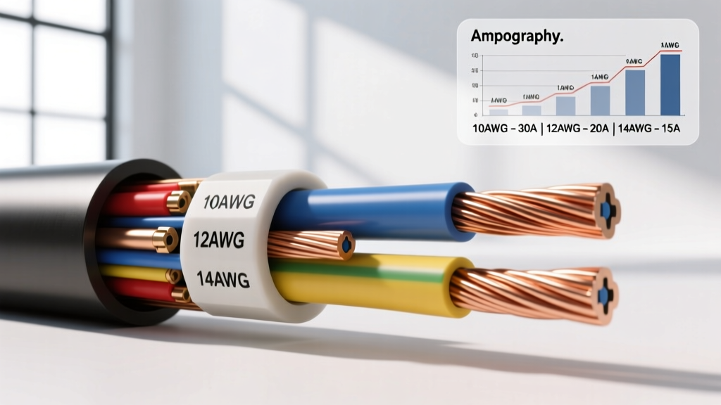
The Physics of Upgrades: Why the Difference in Wire Gauge Matters
When executing high-draw electrical modifications on trucks, off-road vehicles, or custom builds, understanding the difference in wire gauge is the dividing line between a reliable installation and a catastrophic electrical fire. Factory wiring harnesses are engineered with strict weight and cost constraints, typically utilizing 12 AWG to 18 AWG primary wire for standard accessories. However, when you introduce aftermarket components like 12,000 lb winches, high-output alternators, or multi-thousand-watt audio amplifiers, the factory infrastructure becomes a severe bottleneck.
The American Wire Gauge (AWG) system operates on an inverse scale: as the gauge number decreases, the physical diameter and current-carrying capacity (ampacity) of the copper conductor increase. The difference in wire gauge directly correlates to resistance per foot. In a 12-volt DC automotive environment, excessive resistance leads to voltage drop. A voltage drop of just 1.5 volts across a charge wire can prevent a secondary battery from reaching full state-of-charge, while a similar drop on a winch feed will result in massive amperage spikes, overheating the stator and melting PVC insulation.
Automotive Wire Insulation: TXL, SGX, and THHN
Before selecting your gauge, you must select the correct insulation. The difference in wire gauge is irrelevant if the insulation melts on a hot exhaust manifold. For automotive upgrades, avoid standard THHN (building wire) under the hood. Instead, rely on SAE-rated automotive cables:
- TXL (Thin-Wall Cross-Linked): Rated to 125°C. Ideal for routing through tight firewall grommets and under-hood harnesses where space is limited. Commonly used in 10 AWG to 8 AWG for relay feeds and lighting upgrades.
- SGX (Battery and Welding Cable): Rated to 125°C with a thick, heavy-duty EPDM rubber jacket. Highly flexible and extremely resistant to heat, oil, and abrasion. This is the mandatory choice for 4 AWG, 2 AWG, and 1/0 AWG runs to winches and high-amp alternators.
- GXL: Similar to TXL but with slightly thicker insulation, offering a middle ground for heavy-duty chassis routing.
AWG Specification and Voltage Drop Reference Chart
The following chart illustrates the practical difference in wire gauge for high-amperage automotive upgrades. Ampacity ratings are based on SAE J1128 Low Tension Primary Cable Standards for single conductors in free air at an ambient temperature of 25°C (77°F). Voltage drop is calculated for a 10-foot continuous run (20 feet total circuit length including ground) at the specified amperage.
| AWG Size | Strand Count | Max Ampacity (SAE) | Resistance (Ω/1000ft) | Voltage Drop @ 100A (10ft) | Typical Upgrade Application |
|---|---|---|---|---|---|
| 8 AWG | 168 | 80A | 0.641 | 1.28V | Off-road light bars (via 40A relay) |
| 6 AWG | 266 | 120A | 0.403 | 0.80V | Secondary battery isolation feeds |
| 4 AWG | 420 | 160A | 0.253 | 0.50V | High-draw audio amplifiers, Air compressors |
| 2 AWG | 665 | 210A | 0.159 | 0.31V | 10,000 lb Winch power feeds |
| 1/0 AWG | 1064 | 285A | 0.100 | 0.20V | 250A+ High-Output Alternator charge wires |
Source reference: Data extrapolated from DC Power Inc. Ampacity and Voltage Drop Charts and SAE J1128 specifications.
Heavy-Duty Mod Case Study: 12,000 lb Winch Power Feed
A common and dangerous mistake in off-road builds is underestimating the peak amperage of a winch motor. A 12,000 lb winch pulling at maximum rated line pull on the first layer of the drum can draw upwards of 400 to 450 amps. If you attempt to feed this load using 8 AWG wire—perhaps reusing an old jumper cable or undersized marine wire—the difference in wire gauge will manifest as extreme resistance.
At 400 amps, an 8 AWG wire (0.641 Ω/1000ft) over a 15-foot run to the front bumper will generate a voltage drop of over 3.8 volts. The winch motor will receive only 8.2 volts under load, causing it to bog down, draw even more amperage to compensate, and rapidly overheat. Furthermore, the 8 AWG PVC insulation will soften and melt against the chassis.
The Correct Specification
For a 12k winch, you must use 2 AWG SGX welding cable. The heavy EPDM jacket withstands under-hood radiant heat and physical abrasion against the frame. Route the 2 AWG positive cable from the primary battery (or winch isolation solenoid) to the winch motor. For the ground, do not rely on the vehicle's frame as a return path for 400 amps; run a dedicated 2 AWG ground cable directly from the winch motor negative terminal to the engine block or battery negative.
Termination and Overcurrent Protection
Terminate the 2 AWG cable using heavy-duty, tinned copper closed-end ring terminals (3/8" stud size). Crimp using a 6-ton hydraulic crimper with hex dies. Seal the termination with 3:1 shrink ratio, dual-wall adhesive-lined heat shrink (polyamide inner lining) to prevent moisture ingress and copper oxidation. Install a 500-amp ANL fuse or a heavy-duty motorized cutoff solenoid (like the WARN 62132) within 12 inches of the battery positive terminal to protect the 2 AWG feed in the event of a dead short.
Charging System Mod: 250-Amp High-Output Alternator
When upgrading from a factory 140-amp alternator to a 250-amp or 300-amp unit (such as those from Mechman or Power Bastards) to support massive lighting arrays or audio systems, the factory charge wire is entirely inadequate. Factory charge wires are typically 6 AWG or 8 AWG, designed strictly for the OEM alternator's maximum output. The difference in wire gauge between a factory 6 AWG and a required 1/0 AWG is massive in terms of cross-sectional copper area.
If you push 220 amps through a 15-foot run of 6 AWG wire, you will experience a 1.3-volt drop. Your alternator will output 14.4 volts, but your primary battery and main distribution bus will only see 13.1 volts. The vehicle's ECU will interpret this as a failing charging system, potentially triggering a Check Engine Light (CEL) or causing the transmission to enter limp mode due to low system voltage.
Alternator Pinouts and Sense Wire Upgrades
Upgrading the main charge wire to 1/0 AWG SGX is only half the battle. You must also address the alternator's control plug. On popular GM-style AD244 or CS130D high-output alternators, the 4-pin connector utilizes specific circuits:
- Pin L (Lamp): 14 AWG, typically Brown or Yellow. Provides initial excitation voltage from the ignition switch.
- Pin F (Field): Used for PWM control by the ECU on newer models.
- Pin P (Phase): Tachometer signal output.
- Pin S (Sense): 14 AWG, typically Red or White. This is the most critical wire in the harness.
The Sense wire dictates the alternator's voltage regulation. It must be routed directly to the positive battery terminal or the main distribution busbar, not spliced into the alternator's B+ output post. If the Sense wire reads low voltage due to a poor connection or undersized gauge, the alternator will overcharge, boiling the battery. Always use high-quality, sealed Deutsch DT or Metri-Pack connectors for the pigtail, and apply dielectric grease to prevent terminal fretting corrosion.
Failure Modes: Ignoring Wire Gauge Differences
When modifiers ignore the critical difference in wire gauge, the vehicle exhibits specific, diagnosable failure modes:
- Insulation Off-Gassing and Melting: PVC insulation (THHN) subjected to amperages beyond its thermal rating will melt, pool, and eventually expose bare copper, leading to chassis shorts and vehicle fires.
- ECU Resets and Sensor Ghosting: High resistance in undersized ground wires causes ground loops. A 14 AWG ground wire shared between an ECU and a high-draw fuel pump will cause the ECU ground reference to float, resulting in erratic O2 sensor readings and misfires.
- Terminal Galvanic Corrosion: Undersized wires forced into oversized lugs, or poorly crimped connections, allow oxygen and moisture to enter the copper strands. This creates copper oxide, a semiconductor that further increases resistance and heat in a vicious cycle.
Professional Crimping and Termination Standards
A proper wire gauge selection is useless if the termination is flawed. According to Painless Performance Technical Tips and IPC/WHMA-A-620 wiring standards, soldering large-gauge automotive wire (4 AWG and larger) is strongly discouraged in high-vibration environments. Solder wicks into the copper strands, creating a rigid section that is highly susceptible to work-hardening and snapping under engine vibration.
Instead, use high-strand-count copper lugs and a hydraulic hex-crimp tool. The hex crimp applies uniform, 360-degree pressure, cold-welding the copper strands to the lug barrel while maintaining flexibility. When bolting the lugs to a busbar or battery terminal, use a calibrated torque wrench. A 3/8" copper lug on a brass busbar should be torqued to 10-12 ft-lbs. A 5/16" lug requires 7-9 ft-lbs. Always use a split-ring lock washer or a Nord-Lock wedge-locking washer to prevent thermal cycling from loosening the connection over time.
Summary
Whether you are wiring a dual-battery system for overlanding, installing a massive winch, or upgrading your charging system, respecting the difference in wire gauge is non-negotiable. Calculate your total continuous and peak amperage, measure the total circuit length (positive and negative), and consult SAE ampacity charts to select the proper AWG. Combine heavy-gauge SGX or TXL wire with hydraulic crimps and proper overcurrent protection to ensure your modified vehicle performs flawlessly in the harshest conditions.