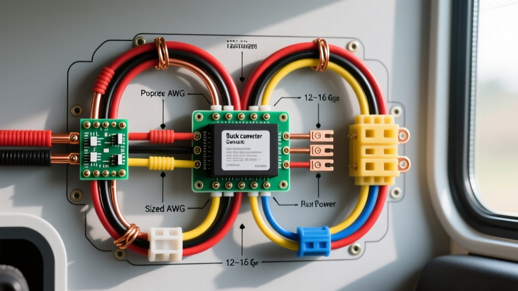
Architecting a 12V DC Ring Camera Installation for Off-Grid Vehicles
When securing off-grid vehicles, boondocking RVs, or overland expedition rigs, integrating smart security systems presents a unique electrical engineering challenge. A standard ring camera installation in a residential setting relies on 120V AC wall power or proprietary battery packs. However, in an automotive or marine environment, relying on the vehicle's alternator or a finite deep-cycle battery bank requires a radically different approach. This advanced technical guide details how to properly hardwire a 12V DC ring camera installation using a step-down buck converter, a low-voltage disconnect (LVD) relay, and SAE-compliant wiring practices to ensure continuous surveillance without risking catastrophic battery depletion.
Why Bypass the 120V Inverter?
Many RV owners attempt to power IoT devices by leaving a 120V AC inverter running 24/7. This is an inefficient and dangerous practice for off-grid applications. A standard modified sine wave or pure sine wave inverter draws a baseline parasitic current (often 0.5A to 1.5A at 12V) simply to maintain its internal transformers and logic boards. Over a 72-hour boondocking trip, this phantom draw can deplete 30 to 50 Amp-hours from your house bank. Furthermore, the 'Ring Stick Up Cam Plug-In' model operates internally on 5V DC (via a 5V/1A USB power adapter). Converting 12V DC to 120V AC, only to have the camera's wall-wart convert it back to 5V DC, results in a compounded energy loss of up to 35%. By utilizing an isolated 12V-to-5V DC-DC buck converter, we eliminate the inverter overhead, achieving near 95% step-down efficiency and drastically reducing the amperage draw on the auxiliary battery bank.
Component Specifications and SAE Standards
Automotive environments are subject to severe vibration, thermal cycling, and corrosive elements. All wiring must comply with SAE J1128 standards for low-tension primary cable. We recommend using TXL (cross-linked polyethylene) wire or marine-grade tinned copper wire to prevent black-wire corrosion. Below is the required bill of materials for a professional-grade installation.
| Component | Specification | Purpose |
|---|---|---|
| Primary Wire | 14 AWG TXL or Tinned Copper | Main trunk from aux battery to buck converter |
| Secondary Wire | 18 AWG TXL | 5V DC output to camera termination |
| Circuit Protection | 15A ATC/ATO Blade Fuse | Inline source protection (Blue Sea Systems) |
| Step-Down Converter | 12V to 5V 3A Isolated Buck | Provides 15W max (10W overhead for WiFi TX spikes) |
| LVD Relay Module | Adjustable 11.8V - 12.5V Cutoff | Prevents deep discharge of AGM/LiFePO4 banks |
| Connectors | Deutsch DT / Heat-Shrink Butt | Vibration-resistant, waterproof terminations |
Comprehensive Wiring Diagram and Pinout Logic
The following circuit logic outlines the precise sequence of power delivery, ensuring that the camera receives clean, regulated 5V DC while protecting the vehicle's auxiliary battery from irreversible sulfation (AGM) or BMS lockout (LiFePO4).
Phase 1: Source Protection and Low-Voltage Disconnect (LVD)
Begin at the auxiliary house battery bank. Never connect directly to the chassis starter battery, as the camera's continuous draw and WiFi transmission bursts can interfere with the vehicle's CAN bus system and ECU logic. Run 14 AWG wire from the positive busbar to an inline 15A ATC fuse holder, mounted within 7 inches of the power source as mandated by Blue Sea Systems circuit protection guidelines. From the fuse, route the wire to the INPUT terminal of your Low-Voltage Disconnect (LVD) module. The LVD is a solid-state relay that continuously monitors battery voltage. If your system uses AGM batteries, set the LVD cutoff to 11.8V. If you are running a Lithium Iron Phosphate (LiFePO4) bank, set the cutoff to 12.5V to preserve cycle life. The LVD OUTPUT will feed the 12V IN (+) terminal of the buck converter.
Phase 2: DC-DC Step-Down Conversion
Mount the isolated 12V-to-5V buck converter in a ventilated, dry compartment (e.g., under a bench seat or inside a rear cabinet). Connect the LVD output to the converter's VIN+. Connect the converter's VIN- to a dedicated common ground busbar, NOT to the vehicle's aluminum chassis skin. Using the chassis as a ground return for sensitive IoT electronics often introduces ground loop noise, which can degrade the 2.4GHz WiFi signal integrity of the camera. The buck converter will step the 12.8V-14.4V input down to a stable 5.0V DC output. Use a multimeter to verify the VOUT+ and VOUT- terminals read exactly 5.0V to 5.1V before connecting the camera.
Phase 3: Device Termination and Weatherproofing
The Ring Stick Up Cam Plug-In utilizes a micro-USB or USB-C barrel connection. Instead of cutting the factory cable (which voids the warranty and compromises the IP65 weather seal), use a high-quality, shielded USB pigtail. Route the 18 AWG wires from the buck converter's VOUT terminals through a rubber grommet to the exterior mounting location. Solder and seal the USB pigtail's power and ground wires to your 18 AWG TXL run using marine-grade heat shrink. For exterior penetrations, apply a bead of marine silicone (e.g., Sikaflex-291) around the grommet to prevent capillary water intrusion into the RV cavity.
Voltage Drop Calculations in Long-Wheelbase Vans and RVs
One of the most frequent failure modes in aftermarket RV camera installations is voltage brownout caused by undersized wire over long distances. If you are mounting a camera on the rear bumper of a 25-foot Airstream or a long-wheelbase Sprinter van, the round-trip wire length can easily exceed 60 feet. According to standard electrical formulas, Voltage Drop (VD) = (2 x Length x Current x Resistance) / 1000.
Let us calculate the drop for a 60-foot round trip using 18 AWG wire (Resistance = 6.38 ohms/1000ft) drawing 1 Amp (the camera's peak WiFi transmission draw):
VD = (2 x 30 x 1 x 6.38) / 1000 = 0.38 Volts.
While 0.38V seems negligible, if your auxiliary battery is resting at 12.0V, the buck converter will only see 11.62V. Many cheap, non-isolated buck converters experience 'dropout' or thermal throttling when input voltage falls below 11.5V, causing the camera to reboot endlessly. By upgrading the main trunk to 14 AWG (Resistance = 2.52 ohms/1000ft), the voltage drop is reduced to a mere 0.15V, ensuring the buck converter operates well within its optimal efficiency curve.
Advanced Troubleshooting: Ground Loops and Parasitic Draws
Even with a flawless schematic, real-world automotive environments introduce variables that can disrupt IoT performance. Use this diagnostic decision tree to resolve common post-installation anomalies:
- Symptom: Camera connects to WiFi but drops offline every 45 minutes.
Cause: Thermal throttling of the buck converter due to mounting in an unventilated, sun-exposed exterior wall cavity.
Fix: Relocate the buck converter to an interior, climate-controlled cabinet and extend the 5V DC 18 AWG secondary wire to the camera. - Symptom: Severe 2.4GHz WiFi interference; camera shows 'Poor RSSI' despite being 15 feet from the router.
Cause: Ground loop interference. The camera's ground is tied to the chassis, while the router's ground is tied to the inverter/battery bus, creating an alternating magnetic field that disrupts the antenna.
Fix: Ensure the buck converter is an isolated topology model, and tie all negative returns to a single, centralized copper ground busbar bonded directly to the battery negative terminal. - Symptom: Auxiliary battery is dead after 4 days of storage.
Cause: The LVD module's internal logic board is drawing excessive parasitic current, or the LVD cutoff threshold was set incorrectly for the battery chemistry.
Fix: Measure the LVD standby draw with a micro-amp multimeter. If it exceeds 5mA, replace it with a solid-state marine LVD. Verify cutoff settings match the battery manufacturer's minimum discharge voltage specifications.
By adhering to these advanced electrical principles, your 12V DC ring camera installation will provide robust, reliable security for your overland rig or RV, surviving the harshest trails and longest boondocking expeditions without compromising your vehicle's vital electrical reserves.