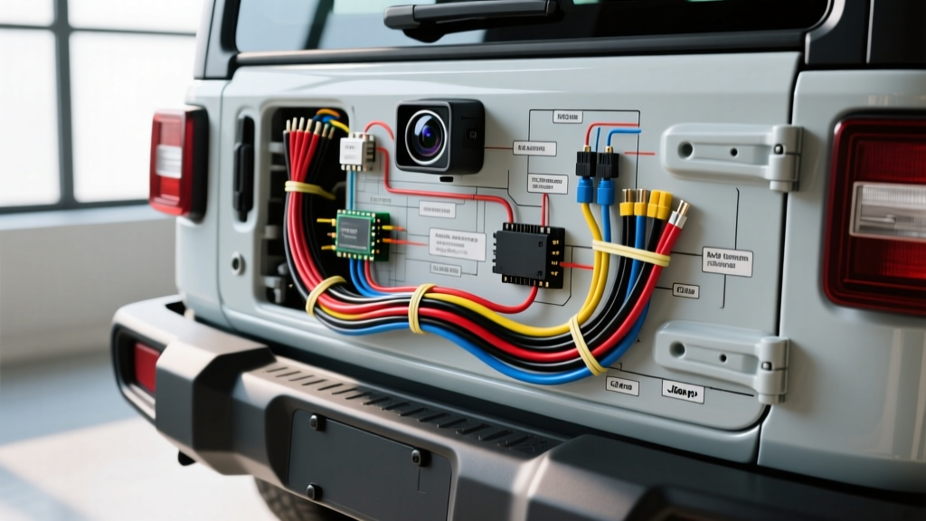
The Wrangler’s Unique Electrical Quirks
Jeep Wranglers are iconic off-road machines, but their electrical architectures present unique hurdles for aftermarket integrators. When installing a backup camera in a Jeep Wrangler, technicians and DIYers frequently run into issues ranging from CAN-bus network faults to severe ground loop interference. The transition from the JK generation (2007–2018) to the JL generation (2018–present) fundamentally changed how the vehicle handles rear lighting and accessory triggers. This guide highlights the most critical wiring mistakes, safety warnings, and diagnostic solutions to ensure a clean, factory-grade camera installation.
Mistake #1: Tapping the JL Reverse Light Without a CAN-bus Decoder
The most catastrophic error made during a JL Wrangler camera install is tapping the reverse light circuit using a standard T-tap or scotch lock. Unlike the older JK generation, which uses a conventional 12V switched circuit from the Totally Integrated Power Module (TIPM), the JL Wrangler utilizes a multiplexed LIN (Local Interconnect Network) and CAN-bus system managed by the Body Control Module (BCM).
The Failure Mode
If you tap the JL reverse light wire (often White/Violet at the taillight harness) directly to power your camera’s reverse trigger, you introduce a parasitic load. The BCM continuously monitors circuit resistance and voltage drop. Detecting the anomaly, the BCM will throw a diagnostic trouble code (DTC) such as U0140, shut down the reverse light circuit entirely to protect the module, and potentially trigger a hyper-flash or dash cluster warning.
The Expert Fix
Never splice directly into a JL multiplexed lighting wire. Instead, use an inductive current clamp trigger or a dedicated CAN-bus signal decoder (such as the PAC TR-4 or a Mopar OBD-II trigger module). These devices read the magnetic field around the wire or intercept the CAN-bus data packet without adding electrical resistance to the factory circuit. For the JK generation, tapping the White/Light Green (WT/LG) wire at the C304 taillight connector is generally safe, provided you use a Posi-Tap connector rather than a piercing T-tap, which invites corrosion.
Mistake #2: Pinching the RCA and Power Harness in the Tailgate Hinge
Routing wires from the body to the tailgate is a notorious pain point on all Wrangler models. The flexible rubber conduit (C-pillar to tailgate boot) is already packed with the factory rear wiper, defroster, and third brake light wiring.
The Failure Mode
Forcing an RCA barrel connector and unlooomed 18 AWG wire through this tight rubber boot inevitably leads to pinched jackets, exposed copper, and eventual short circuits against the steel body. Furthermore, the constant articulation of the tailgate hinge causes friction fatigue, snapping poorly routed wires within months.
The Expert Fix
- Wire Selection: Use 18 AWG TXL (cross-linked polyethylene) wire for the camera power. TXL has a thinner insulation wall than standard PVC but offers superior abrasion and heat resistance.
- Shielding: Wrap the RCA cable and power wires in corrugated split loom, then over-wrap with Tesa 51036 PET fleece tape. This prevents the harness from squeaking against the rubber boot and provides a secondary abrasion barrier.
- Fish Tape Technique: Use a blunt-nose fiberglass fish tape and a non-silicone wire pulling lubricant. Never force the RCA connector; if it snags, detach the barrel and pull the bare cable, reassembling the connector on the cabin side.
Mistake #3: Grounding the Camera Shield to the Aluminum or Painted Hinge
Video static, rolling horizontal bars, and poor low-light performance are almost always traced back to improper grounding. Many installers lazily ground the camera’s black wire or RCA shield to the nearest tailgate bolt.
The Failure Mode
The Wrangler’s tailgate is mounted via heavy-duty hinges, but the mating surfaces are painted or powder-coated, creating high electrical resistance. Furthermore, the camera housing contains a DC-DC buck converter to step down 12V to the 3.3V or 5V required by the CMOS sensor. This switching circuit generates high-frequency noise. If the RCA shield is grounded at the camera end (or at a poor tailgate ground), this noise travels down the shield directly into the head unit’s video input, creating a classic ground loop.
The Expert Fix
According to SAE J1113 standards for electromagnetic compatibility, video coaxial shields should be grounded at the source (the head unit) and isolated at the camera. Run a dedicated 16 AWG ground wire from the camera’s power pigtail all the way back to a verified clean chassis ground near the head unit, or tie it into the head unit’s ISO harness ground (Pin 8 on standard aftermarket harnesses).
Wrangler Reverse Camera Wiring Specification Chart
Reference this table before cutting or splicing any wires on your Wrangler project.
| Generation | Reverse Trigger Source | Wire Color / Pin | AWG Req. | CAN-bus Decoder Needed? |
|---|---|---|---|---|
| JK (2007-2018) | Taillight Harness (C304) | WT/LG (White/Light Green) | 18 AWG TXL | No |
| JL (2018-Present) | BCM / CAN-bus Network | N/A (Use OBD/CAN Tap) | 18 AWG TXL | Yes (Mandatory) |
| JK (Aftermarket LED) | Flasher Relay / BCM Tap | Varies by LED Brand | 16 AWG GXL | Often (PWM Anti-Flicker) |
Mistake #4: Ignoring IP Ratings and Connector Sealing
Wranglers are subjected to high-pressure car washes, deep water fording, and abrasive dust. Using a standard indoor RCA barrel connector or failing to seal the 18 AWG power splices guarantees water ingress.
The Expert Fix
Ensure your camera carries an IP69K rating, not just IP67. IP69K ensures the camera can withstand high-pressure, high-temperature steam cleaning. For the wiring connections, use adhesive-lined dual-wall heat shrink (3M or equivalent). When heated, the inner thermoplastic adhesive melts and seals the wire jacket, preventing capillary action from wicking water into the copper strands. Apply dielectric grease inside the RCA connection before mating, and wrap the joint in self-amalgamating silicone tape.
Diagnostic Decision Tree: Troubleshooting Camera Failures
Use this structured diagnostic tree when the installation yields abnormal results. For deeper schematic references, always consult Mopar TechAuthority wiring diagrams specific to your VIN.
- Symptom: Rolling horizontal bars on the display.
Cause: Ground loop / alternator whine.
Fix: Isolate the RCA shield at the camera. Verify head unit ground is tied to a bare metal chassis point, not a painted dash brace. - Symptom: Camera powers on, but head unit does not switch to the reverse screen.
Cause: Voltage drop on the reverse trigger wire (head unit requires >11V to trigger).
Fix: Install a standard Bosch-style 12V 30A relay. Use the reverse light wire to trigger Pin 85, ground Pin 86, supply 12V constant to Pin 30, and run a new 18 AWG wire from Pin 87 to the head unit's reverse trigger input. - Symptom: JL Reverse lights turn off when shifted into reverse; camera stays dead.
Cause: BCM overcurrent protection tripped due to direct splicing.
Fix: Remove the direct tap. Clear DTCs via an OBD-II bidirectional scanner. Install a non-invasive CAN-bus signal interceptor.
Final Safety Warnings
Always disconnect the negative battery terminal before splicing into any Wrangler wiring harness. In JL models, wait a full 10 minutes after battery disconnect to allow the BCM and Uconnect modules to enter sleep mode; interrupting a module during a write-cycle can corrupt the gateway configuration. For more integration best practices, refer to the Crutchfield automotive tech database for head-unit specific trigger tolerances. By respecting the Wrangler’s unique electrical boundaries and environmental demands, your backup camera will operate flawlessly on the street and the trail.