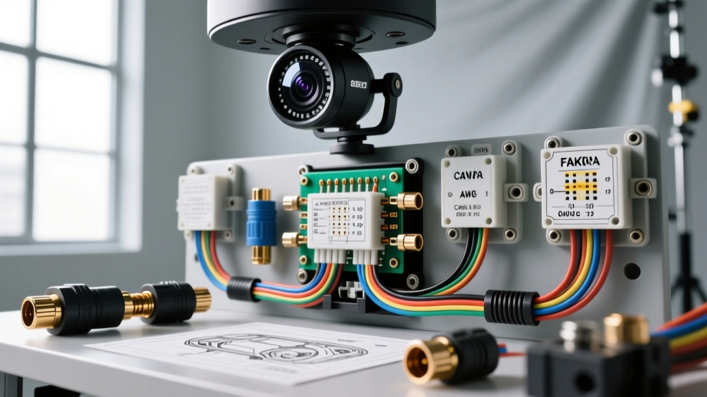
System Architecture & Component Overview
A comprehensive 360 car camera installation requires integrating four ultra-wide-angle (typically 185-degree FOV) fish-eye lenses with a central Image Processing Unit (IPU) or Electronic Control Unit (ECU). Unlike standard single-channel backup cameras, a 360-degree surround-view system relies on real-time video stitching algorithms to generate a seamless bird's-eye view. This process demands high-bandwidth coaxial video transmission, stable DC power delivery, and precise Controller Area Network (CAN) bus integration to feed steering angle and vehicle speed data to the ECU.
When performing a 360 car camera installation, technicians must adhere to strict impedance matching, twisted-pair routing, and grounding protocols. Failure to meet these electrical specifications will result in stitching artifacts, electromagnetic interference (EMI), or complete ECU lockouts. This technical reference outlines the exact wiring specifications, pinout configurations, and calibration requirements for universal and OEM-integrated 360-degree camera systems.
ECU Power, Ground, and Ignition Routing
The central processing ECU for a 360-camera system requires three primary power circuits: Constant Battery (BATT+), Switched Ignition (ACC/IGN), and a dedicated high-current chassis ground. Because the ECU is actively processing four simultaneous video streams and performing real-time homography matrix calculations, it can draw peak currents of up to 4.5 amps during initialization and 2.8 amps during steady-state operation.
Power & Ground Specification Table
| Circuit Function | Wire Color (Standard) | AWG Size | Fuse Rating | Connection Point |
|---|---|---|---|---|
| Constant 12V (BATT+) | Red | 16 AWG | 10A (Mini/ATO) | Fuse Panel (Always Hot) |
| Switched 12V (ACC/IGN) | Yellow | 18 AWG | 5A (Micro2/Mini) | Fuse Panel (Ignition Controlled) |
| Chassis Ground (GND) | Black | 14 AWG | N/A | Factory Ground Stud (M6 Bolt) |
| Reverse Trigger | Purple | 20 AWG | 3A | Reverse Light Circuit / BCM |
| Left Turn Trigger | Green | 20 AWG | 3A | Left Turn Signal Positive |
| Right Turn Trigger | Brown | 20 AWG | 3A | Right Turn Signal Positive |
Installation Note: Never ground the 360 ECU to sheet metal using a self-tapping screw. The high-frequency processing generates sensitive return currents that require a low-resistance path. Always route the 14 AWG ground wire to an existing, painted-removed factory ground stud, securing it with an M6 flange nut torqued to 10 Nm. For detailed vehicle-specific grounding points, consult Crutchfield's car A/V installation guides or the factory service manual.
FAKRA Coaxial Video Connections & Pinouts
Video transmission from the four exterior cameras to the ECU is handled via FAKRA (Fachkreis Automobil) coaxial connectors. These connectors are designed for automotive environments, featuring a locking mechanism that prevents vibration-induced disconnects and an outer shielding cage that blocks RF interference from ignition coils and alternators.
Most aftermarket 360 car camera installation kits utilize RG-174 or RG-316 50-ohm coaxial cables. It is critical to maintain the 50-ohm impedance throughout the entire run. Crimping or sharply bending the cable (bend radius must not exceed 1.5 inches) will alter the dielectric spacing, causing signal reflection and resulting in 'ghosting' or tearing in the stitched 360-image.
FAKRA Connector Color Coding & Mapping
| Camera Position | FAKRA Key/Color Code | Cable Type | Max Run Length |
|---|---|---|---|
| Front (Grille) | Z (Water Blue) | RG-174 Coax | 7.0 Meters |
| Rear (License Plate) | A (Black) | RG-174 Coax | 6.5 Meters |
| Left (Mirror) | B (White) | RG-174 Coax | 5.5 Meters |
| Right (Mirror) | C (Beige) | RG-174 Coax | 5.5 Meters |
Technical Insight: While OEM manufacturers use specific keyed FAKRA connectors (A, B, C, Z) to prevent mis-plugging, many universal aftermarket 360 systems use standard Z-type (Water Blue) connectors for all four channels, relying on color-coded heat shrink tubing near the ECU pigtail for identification. Always verify the physical pinout on the ECU schematic before connecting, as swapping the left and right mirror feeds will cause catastrophic failures in the stitching algorithm during calibration.
CAN Bus Integration & Trigger Signal Routing
To dynamically adjust the trajectory guidelines and properly stitch the images when the vehicle is turning, the 360 ECU must read the Steering Angle Sensor (SAS) and vehicle speed data via the CAN bus. This requires tapping into the vehicle's High-Speed CAN network, which operates at 500 kbps according to the SAE J1939 standard or ISO 11898-2.
CAN Bus Wiring Specifications
- CAN-High (CAN-H): Typically White or Pink wire. Connects to OBD-II Pin 6 or the factory head unit CAN-H line.
- CAN-Low (CAN-L): Typically Green or Purple wire. Connects to OBD-II Pin 14 or the factory head unit CAN-L line.
- Twisted Pair Requirement: The CAN-H and CAN-L wires must be twisted together at a rate of 1 twist per inch to maintain common-mode noise rejection. Never run CAN bus wires parallel to high-current amplifier power cables.
- Termination: The vehicle's CAN bus relies on 120-ohm termination resistors at each end of the network. If your 360 ECU requires a dedicated CAN bus interface module (e.g., a PAC or Axxess data bus interface), ensure the module does not introduce a third 120-ohm resistor into the circuit, which will drop the total resistance to 40 ohms and cause network-wide communication faults.
Trigger Signal Logic
The system uses 20 AWG trigger wires to dictate which camera view is prioritized on the display. The Reverse Trigger (Purple) requires a +12V DC signal. On modern vehicles with Pulse Width Modulated (PWM) reverse light circuits or CAN-controlled lighting modules, you must use a 12V DC relay or a dedicated PWM-to-DC converter to provide a clean +12V trigger to the ECU. Feeding a PWM signal directly into the ECU trigger pin will cause the 360-view to rapidly flicker or fail to engage.
Calibration Grid Specifications & Homography Matrix
Once the physical wiring is complete, the 360 car camera installation requires software calibration to map the 2D fish-eye images onto a 3D virtual bowl model. This is achieved using physical calibration mats placed around the vehicle.
Calibration Mat Placement Rules
- Mat Dimensions: Standard calibration mats feature an alternating black and white checkerboard pattern. The outer dimensions must be exactly 800mm x 800mm, with individual squares measuring 100mm x 100mm.
- Placement Distance: The inner edge of the front and rear mats must be placed exactly 300mm from the vehicle's front and rear bumpers. The side mats must be placed 200mm from the outer edge of the side mirrors.
- Suspension Height: Calibration must be performed with the vehicle on a perfectly level surface, with tire pressures set to factory specifications and a full tank of fuel. If the vehicle is later lifted or lowered by more than 1.5 inches, the homography matrix will be skewed, resulting in visible 'seams' or overlapping artifacts in the 360-degree stitched image.
Troubleshooting Signal Degradation & EMI
Even with perfect pinout adherence, environmental factors can disrupt a 360 car camera installation. Below is a diagnostic decision tree for common electrical failures:
- Symptom: Alternator whine or horizontal scrolling bars on one specific camera feed.
Cause: Ground loop or compromised FAKRA shielding.
Fix: Install a 50-ohm coaxial ground loop isolator on the affected FAKRA line. Verify that the camera housing is not grounding out against the metal license plate bracket; use a rubber isolation gasket. - Symptom: ECU boots, but the 360-stitched view is warped or shows black voids between camera sectors.
Cause: CAN bus data loss (Steering Angle Sensor not communicating).
Fix: Use an oscilloscope to verify the CAN-H and CAN-L differential voltage. CAN-H should idle at 2.5V and rise to 3.5V; CAN-L should idle at 2.5V and drop to 1.5V. If the signal is flat, check for a short to ground in the twisted pair routing. - Symptom: System randomly reboots when the turn signal is activated.
Cause: Voltage drop on the ACC circuit due to undersized wiring or a shared fuse tap.
Fix: Move the ACC fuse tap to a dedicated, low-draw ignition circuit (e.g., the radio or wiper motor fuse) and ensure the wire gauge is at least 18 AWG.
For advanced integration techniques and module programming, refer to Rosen Automotive installation resources, which provide excellent supplemental data on integrating aftermarket 360-ECUs with factory infotainment head units via LVDS (Low-Voltage Differential Signaling) or composite video bypass harnesses.