Introduction to Overland and RV Camera Integration
Integrating smart home security devices into a 12-volt DC automotive, RV, or overland environment requires bridging two entirely different electrical domains. While most residential installation guides assume access to a standard 120V AC mains supply, automotive and RV integrators must engineer a safe, reliable step-up conversion system. When studying the standard ring floodlight camera wiring diagram, most homeowners simply connect to an existing exterior junction box. However, for camper vans, expedition trucks, and off-grid RVs, you must design a system that accounts for voltage drop, vibration, pure sine wave requirements, and weatherproofing.
This beginner-friendly fundamentals guide breaks down the exact wiring specifications, AWG requirements, and component selections needed to safely wire a Ring Floodlight Cam to an automotive 12V DC auxiliary battery system via a hardwired inverter. We will cover both the 12V DC source side and the 120V AC load side, ensuring your setup meets marine and RV electrical safety standards.
Understanding the Power Domain: 12V DC to 120V AC
The Ring Floodlight Cam Wired requires a continuous 110-240 VAC supply, drawing a maximum of 0.25 Amps (approximately 30 Watts). In a 12V DC vehicle environment, this means you must utilize an inverter. However, you cannot simply tap into a cigarette lighter socket or use a cheap, off-the-shelf power converter. The camera's internal switching power supply is highly sensitive to waveform distortion and voltage fluctuations.
The Pure Sine Wave Inverter Mandate
For any automotive camera integration, you must use a Pure Sine Wave (PSW) inverter. Modified Sine Wave (MSW) inverters output a choppy, stepped waveform that mimics AC power but introduces severe harmonic distortion. Connecting a Ring camera to an MSW inverter will result in three critical failures:
- Power Supply Degradation: The camera's internal AC-to-DC rectifier will overheat and prematurely fail due to harmonic clipping.
- Wi-Fi Interference: MSW inverters generate massive electromagnetic interference (EMI) on the 2.4GHz spectrum, effectively jamming the camera's Wi-Fi antenna and preventing video streaming.
- Flickering Artifacts: The LED floodlights will exhibit a visible strobe effect on the camera sensor, ruining night vision capabilities.
Select a PSW inverter rated for at least 400W continuous output to handle the initial surge current of the camera's LED drivers and internal capacitors upon startup.
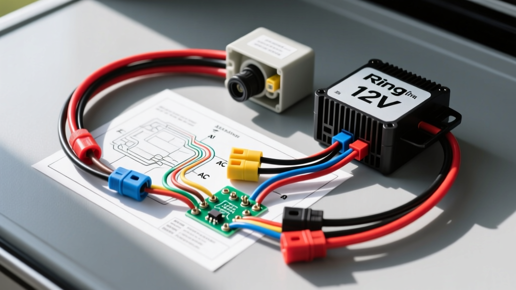
Comprehensive Ring Floodlight Camera Wiring Diagram
The wiring process is divided into two distinct phases: the high-current 12V DC feed from your auxiliary battery to the inverter, and the low-current 120V AC feed from the inverter to the camera's junction box.
Phase 1: The 12V DC Source to Inverter Feed
The DC side of your diagram requires heavy-gauge wire to prevent voltage drop, which can cause the inverter's low-voltage alarm to trigger when the camera's floodlights activate. According to ABYC (American Boat and Yacht Council) E-11 standards, voltage drop on critical DC circuits should not exceed 3%.
- Wire Selection: Use 8 AWG marine-grade, tinned stranded copper wire (such as Ancor or Windy Nation). Tinned copper resists the green oxidation (copper sulfate) common in humid or outdoor automotive environments.
- Overcurrent Protection: Install a 30A ANL fuse on the positive (red) wire within 18 inches of the auxiliary battery's positive terminal. This protects the wire run from shorting against the vehicle chassis.
- Termination: Crimp 3/8-inch heat-shrink ring terminals onto the wire ends using a ratcheting crimper. Apply adhesive-lined heat shrink to seal the connection against moisture. Connect the negative (black) wire to a dedicated negative bus bar, never directly to the battery negative terminal if multiple accessories are present.
- Inverter Chassis Ground: Run a separate 10 AWG green wire from the inverter's chassis ground lug to the vehicle's bare metal frame. Use a star washer to bite through the paint and ensure a zero-resistance ground path.
Phase 2: The 120V AC Junction Box Integration
The AC side of the Ring Floodlight Camera wiring diagram mimics a standard residential setup but requires automotive-grade vibration mitigation. Standard twist-on wire nuts will vibrate loose over time while driving off-road.
- Junction Box Prep: Mount a NEMA 3R weatherproof, non-metallic junction box to the exterior of the RV or truck bed. Non-metallic boxes prevent EMI shielding issues that can block the camera's Wi-Fi signal.
- AC Wire Selection: Run 12 AWG THHN/THWN stranded copper wire from the inverter's AC output terminal block to the junction box. While 14 AWG is technically sufficient for the 0.25A draw, 12 AWG provides superior mechanical strength and abrasion resistance when routing through vehicle bulkheads.
- Vibration-Proof Connectors: Strip the 12 AWG wires and connect them to the Ring camera's pre-attached pigtails using Wago 221-413 lever nuts. These spring-clamp connectors maintain constant tension on the wire, completely eliminating the risk of vibration-induced disconnects.
- Weatherproofing: Fill the bottom of the junction box with a silicone-based dielectric grease or potting compound to prevent condensation from bridging the AC Line and Neutral connections.
Wire Gauge, AWG, and Component Specification Chart
Use the following reference chart to ensure your components meet automotive and RV electrical safety thresholds.
| Circuit Segment | Recommended AWG | Wire Type & Color Code | Connector / Protection |
|---|---|---|---|
| Battery to Inverter (+) | 8 AWG | Tinned Stranded (Red) | 30A ANL Fuse, 3/8" Heat Shrink Ring |
| Battery to Inverter (-) | 8 AWG | Tinned Stranded (Black) | Negative Bus Bar, 3/8" Heat Shrink Ring |
| Inverter Chassis Ground | 10 AWG | Tinned Stranded (Green/Yellow) | Star Washer to Bare Chassis Metal |
| Inverter AC Out (Line) | 12 AWG | THHN Stranded (Black) | Wago 221-413 Lever Nut |
| Inverter AC Out (Neutral) | 12 AWG | THHN Stranded (White) | Wago 221-413 Lever Nut |
| Inverter AC Out (Ground) | 12 AWG | THHN Stranded (Green/Bare) | Wago 221-413 Lever Nut |
Grounding, Isolation, and Metal Body Interference
A frequent point of failure in automotive camera installations is improper grounding and Faraday cage interference. According to the National Electrical Code (NEC) Article 551 regarding RV electrical systems, the AC ground and DC negative must be bonded at a single point (usually the main distribution panel or inverter chassis) to prevent ground loops. If you experience a 60Hz hum in the camera's audio or erratic Wi-Fi drops, check your inverter's neutral-ground bonding configuration. Many off-grid inverters feature a switch or relay to bond Neutral and Ground; this must be engaged for the Ring camera's internal GFCI and safety circuits to read the electrical environment correctly.
Furthermore, if mounting the camera on an aluminum truck cap or steel RV body, remember that metal acts as a Faraday cage. Ensure the camera's Wi-Fi antennas (located near the bottom hinge of the Ring unit) are not pressed flush against bare metal. Use a rubber isolation pad between the camera base and the mounting surface to allow the 2.4GHz signal to propagate outward rather than reflecting back into the metal chassis.
Beginner Troubleshooting: Symptom-Cause-Fix Matrix
- Symptom: Camera goes offline intermittently when driving or when the 12V fridge compressor kicks on.
Cause: Voltage drop on the 12V DC side causing the PSW inverter to momentarily drop AC output voltage below 110V.
Fix: Upgrade the DC feed from 8 AWG to 6 AWG and clean all bus bar connections with contact cleaner. - Symptom: Floodlights flicker rapidly on the camera feed, or the feed shows horizontal rolling bands.
Cause: Use of a Modified Sine Wave (MSW) inverter or a low-quality PSW inverter with high Total Harmonic Distortion (THD).
Fix: Replace the inverter with a premium PSW unit (e.g., Victron or Samlex) with a THD rating of less than 3%. - Symptom: Camera physically mounts but fails to connect to the RV's Wi-Fi network during setup.
Cause: The metal junction box or mounting surface is detuning the internal antenna, or the 12V DC ground is creating EMI.
Fix: Ensure the junction box is non-metallic (polycarbonate) and verify the inverter chassis ground has less than 0.5 ohms of resistance to the battery negative.
Authoritative References
For further reading on automotive electrical safety and smart device integration, consult the following resources:
- Ring Official Support: Floodlight Cam Wired Installation Guide - Provides the baseline AC voltage requirements and junction box mounting templates.
- ABYC E-11 AC & DC Electrical Systems on Boats - The gold standard for 12V DC wire sizing, overcurrent protection, and tinned copper requirements in mobile environments.
- NFPA 70: National Electrical Code (NEC) - Specifically Article 551, which governs AC/DC bonding and grounding requirements for recreational vehicles and mobile platforms.