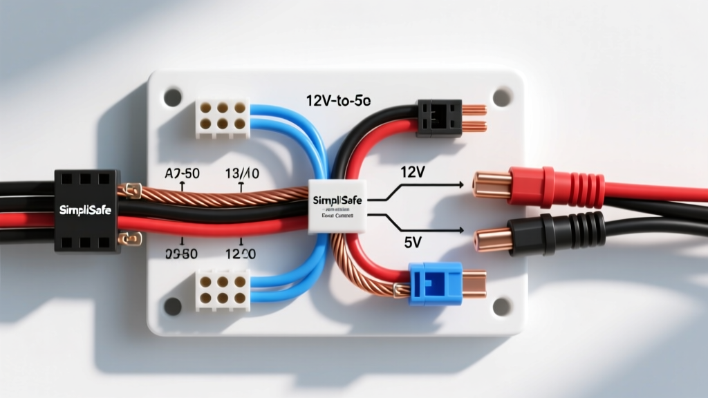
The Challenge: Adapting Home Security for 12V Automotive Systems
When executing an overland van build, fleet security upgrade, or camper conversion, integrating commercial home security hardware into a mobile DC environment requires strict adherence to automotive electrical standards. The SimpliSafe indoor camera is an excellent optical sensor for monitoring vehicle interiors or cargo bays, but it is engineered for 110V AC wall power, stepping down internally via a proprietary adapter to 5V DC at 2A. Attempting a direct SimpliSafe indoor camera installation using cheap, unregulated 12V-to-5V USB adapters often results in logic board failure due to alternator voltage spikes (load dump) and electromagnetic interference (EMI).
To achieve a reliable, permanent installation that survives the harsh electrical noise of a vehicle's charging system, we must bypass the factory AC adapter. This guide details how to safely step down a 12V automotive circuit to a regulated 5V DC output, implement ignition-switched relay logic to prevent parasitic battery drain, and route the wiring according to SAE standards.
SimpliSafe Power Requirements vs. Vehicle Alternator Output
A standard vehicle alternator outputs between 13.5V and 14.4V when the engine is running, and can experience transient load dump spikes up to 40V if a battery connection is abruptly severed while the alternator is spinning. The SimpliSafe camera requires a clean, regulated 5V DC input at a maximum draw of 2A (10W). Feeding this device unregulated power or relying on standard cigarette lighter USB adapters will introduce alternator whine into the camera's microphone and eventually fry the internal voltage regulators.
The solution is to use an automotive-grade, isolated DC-DC buck converter with built-in transient voltage suppression (TVS). Below are the required specifications for the step-down module.
| Parameter | Specification | Notes |
|---|---|---|
| Input Voltage Range | 8.0V - 22.0V DC | Accommodates cranking voltage drops and charging spikes. |
| Output Voltage | 5.0V DC ±0.25V | Strict tolerance required for camera logic board stability. |
| Max Output Current | 3.0A (Continuous) | Provides 50% overhead above the camera's 2A peak draw. |
| Protection Features | OVP, OCP, OTP, Short-Circuit | Over-Voltage, Over-Current, Over-Temperature protections. |
| Efficiency | > 92% | Minimizes heat generation inside enclosed cabinetry. |
Relay Logic for Parasitic Draw Prevention
A common failure mode in aftermarket camera installations is parasitic draw. While the SimpliSafe camera only draws roughly 2W when idle and 8W when recording, leaving it wired to a constant 12V battery source will drain a standard Group 48 starter battery over a week of non-use. If you are wiring into the vehicle's main chassis battery (rather than a dedicated house battery bank with a Low Voltage Disconnect), you must use an ignition-switched relay to cut power when the key is off.
We utilize a standard Bosch ISO Mini Relay (DIN 72552 standard) to control the 12V feed to the buck converter. This ensures the camera only powers up when the ignition is in the "ON" or "ACC" position.
| Pin Number | Function | Automotive Wire Color (GXL) | Connection Point |
|---|---|---|---|
| 30 | Common (Power In) | Red (14 AWG) | Fuse Box Constant 12V (Battery+) |
| 87 | Normally Open (Power Out) | Orange (14 AWG) | Buck Converter 12V Input (+) |
| 86 | Coil Positive (Trigger) | Yellow (18 AWG) | Fuse Box Ignition-Switched 12V |
| 85 | Coil Negative (Ground) | Black (18 AWG) | Chassis Ground Busbar |
| 87a | Normally Closed | Not Used | Tape off and secure. |
Step-by-Step SimpliSafe Indoor Camera Installation Wiring Diagram
Follow this sequence to ensure proper circuit protection, voltage stability, and adherence to Littelfuse automotive relay wiring guidelines.
Step 1: Fuse Tapping and Circuit Protection
Locate the vehicle's interior fuse panel. Using a multimeter, identify a constant 12V fuse (e.g., power seats, hazard lights) for Pin 30, and an ignition-switched 12V fuse (e.g., wipers, radio) for Pin 86. Use an Add-A-Circuit (ATO/ATM) fuse tap. Install a 5A blade fuse on the tap for the camera circuit. Do not share a fuse tap with safety-critical systems like airbags or ABS modules.
Step 2: Routing and Wire Selection
Use SAE J1128 GXL (Cross-linked polyethylene) wire for all 12V runs. GXL wire is rated for 125°C and features thin-wall insulation, making it ideal for routing through tight firewall grommets and behind interior trim panels.
- 12V Main Feed (Pin 30 to 87): 14 AWG GXL. Even though the camera draws minimal current, 14 AWG prevents voltage drop over long runs (e.g., from the engine bay fuse box to the rear cargo area), ensuring the buck converter receives at least 9V under heavy alternator load.
- 5V Output to Camera: 18 AWG SXL. The run from the buck converter to the camera is typically short (under 3 feet), making 18 AWG perfectly adequate for a 2A draw.
Step 3: Crimping and Terminations
Never use solder on automotive wiring that is subject to vibration; solder wicks into the wire strands, creating a rigid point that will eventually fatigue and snap. Instead, use open-barrel crimp terminals with a ratcheting crimper. Seal all connections with dual-wall, adhesive-lined heat shrink (3:1 shrink ratio) to prevent moisture ingress and galvanic corrosion. For the ground connection, use a 1/4-inch ring terminal attached to a bare metal chassis point. Sand the paint away to bare steel, apply a layer of NO-OX-ID A-Special conductive grease, and torque the bolt to 8 Nm.
Step 4: Fabricating the 5V USB-C Pigtail
Since you are bypassing the factory AC adapter, you must supply 5V to the camera's USB-C port. Cut a high-quality, USB-IF certified 5V USB-C cable. Strip the outer jacket to reveal the internal wires. You only need the VBUS (Red) and GND (Black) wires; the data lines (Green/White) are unnecessary for power delivery. Crimp these to the output terminals of your DC-DC buck converter, ensuring correct polarity. A reversed polarity connection will instantly destroy the camera's internal PMIC (Power Management IC).
Troubleshooting Voltage Drop & EMI Interference
Automotive environments are electrically hostile. If your SimpliSafe camera experiences random reboots, offline statuses, or audio hum, consult the following diagnostic matrix based on SAE J1113 Electromagnetic Compatibility standards.
| Symptom | Probable Cause | Diagnostic & Fix |
|---|---|---|
| Camera reboots when engine starts. | Voltage drop below buck converter's 8V threshold during starter cranking. | Measure voltage at Pin 30 during cranking. If it drops below 9V, upgrade the constant 12V feed to 12 AWG or move the tap to a battery-direct terminal with an inline 5A ANL fuse. |
| Alternator whine in camera audio feed. | Ground loop or EMI induction from ignition coils. | Ensure the camera ground and buck converter ground share the exact same star-ground busbar point. Route 5V wiring away from ignition coil harnesses. Add a ferrite bead choke to the 5V USB cable. |
| Buck converter becomes too hot to touch. | Thermal shutdown due to poor ventilation or over-voltage input. | Verify alternator output is not exceeding 14.8V (indicating a bad voltage regulator). Mount the buck converter to an aluminum chassis surface using thermal tape to act as a heatsink. |
| Camera drains battery overnight. | Relay coil back-EMF keeping contacts closed, or wrong fuse tap. | Install a 1N4001 flyback diode across relay pins 85 and 86 (stripe facing Pin 86) to absorb coil collapse voltage. Verify the trigger fuse is truly ignition-switched using a multimeter. |
Advanced Integration: House Battery Banks & Low Voltage Disconnects
If your SimpliSafe indoor camera installation is part of a comprehensive camper van build utilizing a dedicated Lithium Iron Phosphate (LiFePO4) house battery bank, the ignition-switched relay method is unnecessary. Instead, wire the buck converter directly to the house battery's fused distribution bus. To protect the battery from deep discharge, route the positive feed through a Victron Smart BatteryProtect. Set the disconnect threshold to 11.5V. This allows the camera to run 24/7 for security while parked, but automatically severs the ground path if the battery voltage drops to a critical level, preserving enough capacity to run your DC-DC charger or inverter later.
Conclusion
A professional-grade SimpliSafe indoor camera installation in a vehicle requires moving beyond basic plug-and-play USB adapters. By utilizing an isolated DC-DC buck converter, implementing proper Bosch relay logic for parasitic draw prevention, and adhering to SAE crimping and routing standards, you ensure that your security hardware survives the vibration, voltage spikes, and thermal extremes of the automotive environment. Always verify your wiring with a multimeter and perform a 24-hour parasitic draw test before finalizing the interior trim reassembly.