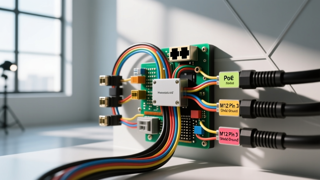
The Shift to Automotive IP Camera Systems
The transition from analog RCA-based backup cameras to digital IP camera install architectures has revolutionized fleet management, RV surveillance, and advanced 360-degree bird's-eye view systems. Unlike traditional analog setups that rely on simple composite video signals, automotive IP (Internet Protocol) cameras transmit high-definition digital data and receive power simultaneously via Power over Ethernet (PoE). While this reduces cable bulk, it introduces severe vulnerabilities to Electromagnetic Interference (EMI), voltage spikes, and CAN-bus backfeeding. A flawed installation will not only result in packet loss and frozen video feeds but can also destroy expensive Network Video Recorders (NVRs) and vehicle Body Control Modules (BCMs). This guide details the most catastrophic wiring mistakes made during automotive IP camera integrations and provides the SAE-compliant solutions required for a bulletproof setup.
Critical IP Camera Install Mistakes & Safety Warnings
1. Ignoring EMI and Shielding Protocols (The Ground Loop Trap)
The most frequent cause of digital artifacting and dropped frames in a mobile IP camera install is Electromagnetic Interference (EMI) generated by the vehicle's alternator, ignition coils, and high-current inverters. Standard unshielded Cat5e/Cat6 cables act as antennas, absorbing alternator whine and corrupting Gigabit Ethernet packets.
The Mistake: Using standard UTP (Unshielded Twisted Pair) patch cables and failing to terminate the shield drain wire, or worse, grounding the drain wire at both the camera and the NVR switch.
The Fix: You must use S/FTP (Shielded Foiled Twisted Pair) Cat6a cable rated for mobile environments (24 AWG stranded copper). The shield drain wire must be terminated to the metal chassis of the M12 connector at the camera end, but left floating (unconnected) at the NVR/PoE switch end. Grounding both ends creates a ground loop, allowing chassis current to flow through the data cable shield, which induces severe 60Hz/120Hz noise and degrades the data signal-to-noise ratio (SNR). Always adhere to SAE J1113 standards for electromagnetic compatibility in vehicle wiring harnesses.
2. Miscalculating PoE Voltage Drop and AWG Limits
Automotive PoE injectors typically step up the vehicle's 12V or 24V DC system to the 48V DC required by IEEE 802.3af/at IP cameras. Installers often underestimate the current draw on the 12V supply side of the PoE injector.
The Mistake: Powering a 4-port PoE gigabit switch (drawing up to 60W total) using 18 AWG wire tapped from a distant fuse box. The voltage drop over 15 feet of 18 AWG wire will cause the input voltage at the PoE injector to drop below its 10.5V under-voltage lockout threshold, causing the cameras to reboot continuously.
The Fix: Calculate the amperage draw on the 12V side. A 60W PoE switch drawing from a 12V system requires roughly 5.5 Amps (factoring in DC-DC conversion inefficiency). For a 15-foot run, you must use a minimum of 14 AWG primary automotive wire (GXL or TXL cross-linked polyethylene insulation) to keep the voltage drop under 0.2V. Always fuse this line within 18 inches of the battery or main power distribution bus with an ATO blade fuse rated at 125% of the continuous load (e.g., a 7.5A fuse).
3. Backfeeding the BCM on Accessory Taps
To trigger the NVR to wake from sleep mode or switch to a specific camera view when the vehicle is put in reverse, installers must tap a reverse light or accessory circuit. Modern vehicles (2018+ Ford Transit, Ram ProMaster, Freightliner Cascadia) do not use simple 12V analog switches for lighting; they use CAN-bus or LIN-bus controlled solid-state relays, often utilizing Pulse Width Modulation (PWM) to monitor bulb health.
The Mistake: Splicing directly into a PWM-controlled reverse light wire to feed the NVR's 12V trigger input. When the NVR's internal pull-up resistor or capacitance interacts with the PWM signal, it can backfeed voltage into the BCM's low-side driver, instantly frying a $1,500 control module.
The Fix: Never splice directly into modern multiplexed lighting circuits. Use a PWM-to-DC filter relay or an automotive logic probe with a high-impedance input. Alternatively, use an OBD-II CAN-bus data interface module to read the reverse gear status digitally and output a clean, isolated dry-contact relay closure to trigger the NVR.
4. Neglecting ISO 7637-2 Load Dump Protection
Commercial vehicles and heavy-duty trucks are notorious for massive voltage transients. When a heavy electrical load (like an A/C compressor or liftgate motor) is suddenly switched off while the alternator is charging at high output, the alternator's field current cannot collapse instantly. This results in a 'load dump'—a massive voltage spike that can exceed 80V and last for hundreds of milliseconds.
The Mistake: Relying solely on the PoE switch's internal fuse for protection. Fuses react to current overloads, not voltage spikes. A load dump will bypass the fuse and instantly vaporize the silicon in the IP camera's PoE receiver chip and the switch's Ethernet PHY.
The Fix: Install a TVS (Transient Voltage Suppression) diode array rated specifically for ISO 7637-2 Pulse 5a/5b load dump survival on the main 12V/24V power feed before it reaches the PoE injector. A bidirectional TVS diode with a clamping voltage of 33V (for 12V systems) or 58V (for 24V systems) will safely shunt the spike to ground, protecting the sensitive IP networking gear.
M12 X-Coded Connector Pinout & PoE Specification Chart
Automotive IP cameras rarely use standard RJ45 jacks, which fail under high-vibration and high-moisture conditions. Instead, the industry standard is the M12 X-Coded 8-pin connector, which supports Gigabit Ethernet and PoE simultaneously while maintaining an IP67/IP69K waterproof seal. Proper crimping requires a specialized ratcheting M12 tool; hand-crimping these pins will result in intermittent data faults.
| M12 X-Code Pin | Wire Color (Cat6a S/FTP) | Signal / Function | PoE Alt-A / Alt-B Power |
|---|---|---|---|
| Pin 1 | White/Orange | TD+ (Transmit Data +) | PWR+ (Alt-A) |
| Pin 2 | Orange | TD- (Transmit Data -) | PWR+ (Alt-A) |
| Pin 3 | White/Green | RD+ (Receive Data +) | PWR- (Alt-A) |
| Pin 4 | Blue | BI_DD+ (Bi-Directional) | PWR- (Alt-B) |
| Pin 5 | White/Blue | BI_DD- (Bi-Directional) | PWR+ (Alt-B) |
| Pin 6 | Green | RD- (Receive Data -) | PWR- (Alt-A) |
| Pin 7 | White/Brown | BI_DC+ (Bi-Directional) | PWR+ (Alt-B) |
| Pin 8 | Brown | BI_DC- (Bi-Directional) | PWR- (Alt-B) |
Note: Always verify the specific IP camera manufacturer's pinout requirements, as some proprietary 360-degree systems utilize non-standard M12 A-coded or D-coded connectors for 100Mbps Fast Ethernet.
Symptom-Cause-Fix Troubleshooting Matrix
When an IP camera install fails post-assembly, use this diagnostic matrix to isolate the fault without blindly replacing expensive components.
| Symptom | Probable Cause | Diagnostic Fix |
|---|---|---|
| Camera powers on, but NVR shows 'Network Unreachable' or packet loss > 20%. | EMI corruption or broken foil shield inside the Cat6a cable. | Test cable with a Gigabit Ethernet certifier. Ensure drain wire is grounded at the camera M12 shell only. Reroute cable away from AC inverters. |
| Camera boots, then drops offline every 45 seconds. | PoE injector under-voltage lockout due to 12V feed voltage drop. | Measure voltage at the PoE injector input terminals under load. If below 11.2V, upgrade 12V feed wire to 12 AWG and check for corroded chassis grounds. |
| NVR reboots randomly when vehicle hits bumps. | M12 connector not fully seated or locking collar not torqued. | Verify M12 X-code alignment key. Tighten locking collar to manufacturer spec (typically 0.6 Nm). Apply marine-grade dielectric grease to the outer threads only, avoiding the data pins. |
| Video feed freezes only when engine is revved. | Alternator diode ripple leaking into the DC-DC PoE power supply. | Install an inline LC (Inductor-Capacitor) noise filter on the 12V power line feeding the PoE switch. Check alternator ground strap. |
SAE Compliance and Environmental Sealing
Beyond electrical safety, physical environmental sealing is paramount. Mobile IP cameras are subjected to high-pressure washdowns, road salt, and extreme thermal cycling. When terminating the rear of an M12 connector or routing cables through a vehicle bulkhead, never rely on standard electrical tape or silicone sealant. Use heat-shrink tubing with an inner layer of polyamide hot-melt adhesive (dual-wall adhesive-lined heat shrink). This creates a watertight, strain-relieved seal that meets ISO 16750-4 standards for climatic loads in road vehicles.
Furthermore, ensure all external camera housings are rated to at least IP69K, which guarantees protection against close-range high-pressure, high-temperature spray downs—a common occurrence in commercial fleet and agricultural environments. By respecting the strict parameters of PoE delivery, digital shielding, and transient voltage suppression, your IP camera installations will deliver uncompromising reliability in the harshest automotive environments.