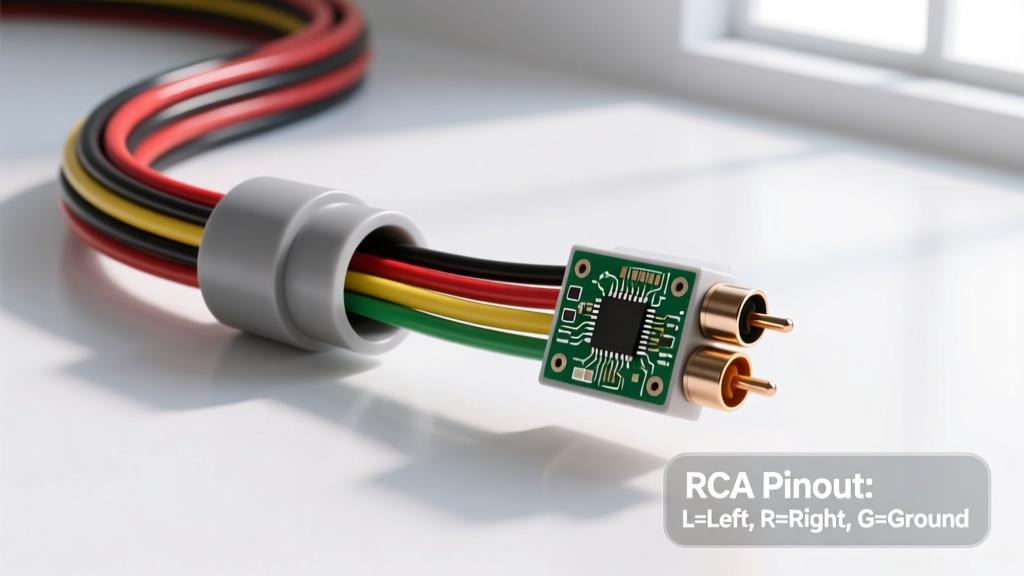
Technical Specifications for Installing Reverse Camera Systems
When installing reverse camera systems in modern vehicles, technicians and DIY installers must bridge the gap between 75-ohm RF video standards and harsh 12V DC automotive environments. A successful integration requires strict adherence to composite video signaling, proper mitigation of Pulse Width Modulation (PWM) on lighting circuits, and adherence to automotive wire gauge standards. This technical specification reference details the exact wiring parameters, pin configurations, and signal conditioning required for a flawless aftermarket or OEM-integration backup camera installation.
RCA Video Signal & Shielding Specifications
Composite video (CVBS) operates on a 1.0V peak-to-peak signal with a 75-ohm characteristic impedance. The standard RCA connector utilized in 99% of aftermarket head units features a center pin for the active video signal and an outer barrel for the signal return (shield/ground). Using unshielded or improperly terminated cables results in high-frequency alternator whine and electromagnetic interference (EMI) from the vehicle's CAN bus network.
Composite Video Pinout & Signal Levels
| Parameter | Specification | Tolerance |
|---|---|---|
| Center Pin (Signal) | Active CVBS Video (NTSC/PAL) | 1.0V p-p into 75Ω |
| Outer Barrel (Shield) | Signal Return / Ground | 0V Reference |
| Sync Tip Level | 0.0V | ± 0.05V |
| Blanking Level | 0.3V | ± 0.05V |
| Peak White Level | 1.0V | ± 0.05V |
Shielding Requirement: Specify 20 AWG to 22 AWG stranded copper with a braided copper shield (minimum 85% coverage). Avoid foil-only shielding, which degrades and fractures when flexed through vehicle door boots, trunk hinges, and firewall grommets. For runs exceeding 15 feet, utilize a dedicated video line driver to maintain the 75-ohm impedance and prevent signal attenuation.
12V Reverse Trigger Circuit & PWM Mitigation
The most common failure point when installing reverse camera setups is the 12V reverse trigger signal. In vehicles manufactured post-2012, particularly European models (BMW, Audi, VW) and modern American trucks, the reverse light circuit is driven by Pulse Width Modulation (PWM) or multiplexed LIN bus signals rather than a steady 12V DC feed. Tapping directly into a PWM reverse light yields a 10Hz to 50Hz square wave, causing the head unit to rapidly cycle the camera input, display a 'No Signal' error, or trigger a check-control bulb-out warning on the dash.
Mitigation Strategy: Automotive Relay Integration
To rectify PWM interference, installers must isolate the head unit trigger using a standard ISO 7588 4-pin automotive relay. The PWM signal is used only to energize the relay coil, while the relay contacts switch a clean, constant 12V DC source to the head unit.
| Relay Pin (DIN 72552) | Function | Wire Color (Standard) | Connection Point |
|---|---|---|---|
| 85 | Coil Ground | Black (18 AWG) | Chassis Star Ground |
| 86 | Coil 12V Input | Green/White (18 AWG) | Reverse Light Positive (PWM Source) |
| 30 | Common (Input) | Red (16 AWG) | Fused 12V Constant or Ignition Source |
| 87 | Normally Open (Output) | Blue (18 AWG) | Head Unit Reverse Trigger Wire |
Note: Always install a 1N4001 flyback diode across pins 85 and 86 (cathode to 86) to suppress inductive voltage spikes that can damage sensitive CAN bus modules or body control modules (BCM).
Power, Ground, and SAE Wiring Standards
Adhering to the SAE J1128 Low Voltage Primary Cable Standard is critical for automotive electrical safety. For reverse camera power runs under 15 feet, 18 AWG stranded copper with GXL (Cross-linked) or TXL insulation is mandatory. These insulation types resist high engine bay temperatures and automotive fluids far better than standard PVC.
Voltage Drop & Grounding Topology
The camera module typically draws between 150mA and 300mA. While this is a low current draw, voltage drop must not exceed 0.5V on the 12V supply line to ensure the internal voltage regulator of the camera operates within spec. Grounding must be executed using a dedicated star-ground topology. Do not share the camera ground with high-current devices like subwoofers, lighting bars, or power seat motors. Sharing a ground path introduces varying voltage potentials, resulting in severe ground loop hum (alternator whine) across the RCA shield.
- Power Wire: 18 AWG GXL Stranded Copper (Red)
- Ground Wire: 18 AWG GXL Stranded Copper (Black)
- Termination: Adhesive-lined heat shrink and ring terminals (No T-taps or Scotchlocks)
- Overcurrent Protection: 2A ATC/ATO blade fuse located within 18 inches of the power source.
Connector Types for Camera Module Integration
Many cheap aftermarket cameras utilize molded, non-waterproof pigtails that fail within one year of exposure to the elements. For professional-grade installations, the camera module should be terminated using sealed automotive connectors. The AMP Superseal 1.5 series or Deutsch DT series (4-pin configuration) are the industry standards for exterior automotive electronics.
Standard 4-Pin Camera Module Pinout (Deutsch DT)
- Pin 1 (Red): +12V DC Power Input
- Pin 2 (Black): Ground / Signal Return
- Pin 3 (White): Video Signal Output (Connects to RCA Center Pin)
- Pin 4 (Green): Trigger / Reverse Sense (Optional, used for internal grid line toggling)
For comprehensive physical installation techniques and routing advice, refer to the Crutchfield Backup Camera Installation Guide, which provides excellent visual references for trunk lid routing and grommet sealing.
Troubleshooting Decision Tree: Signal & Power Faults
| Symptom | Electrical Root Cause | Specification Fix |
|---|---|---|
| Alternator Whine in Video | Ground loop; RCA shield carrying return current from another device. | Isolate camera ground to a dedicated chassis point. Verify RCA shield continuity is unbroken. |
| Camera Flickers / Reboots | PWM signal on reverse trigger wire; voltage dropping below 9V. | Install ISO 7588 relay or a 1000µF / 16V capacitor filter on the trigger line. |
| No Video / Blue Screen | Impedance mismatch or broken center conductor. | Test RCA cable with a multimeter for continuity. Verify 75Ω termination at the head unit. |
| Dash 'Bulb Out' Warning | Relay coil drawing too little current compared to OEM bulb. | Install a 10W power resistor in parallel with the relay coil to simulate bulb load. |