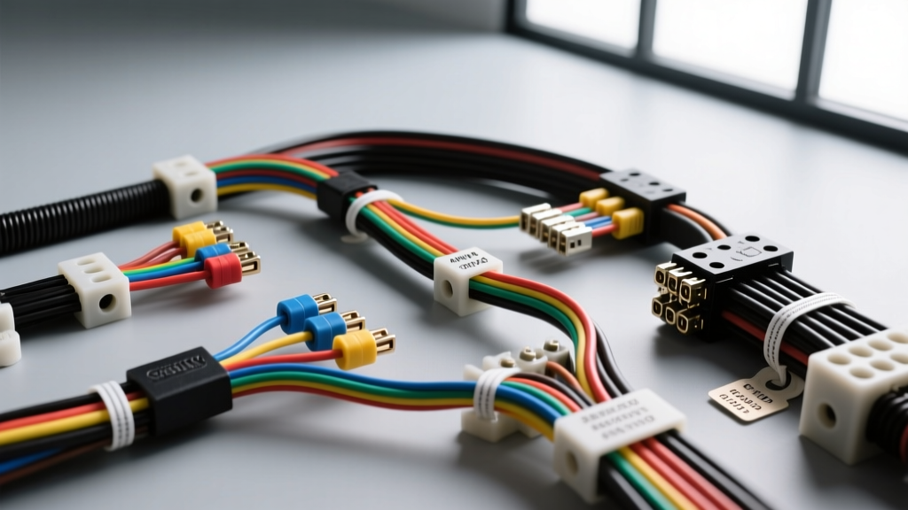
The Reality of Big-Box Store Camera Kits
When DIYers search for a home depot camera installation solution, they are typically purchasing off-the-shelf aftermarket backup or trailer camera kits from brands like Rear View Safety, Voyager, or generic unbranded imports. While these hardware store kits provide adequate lenses and monitors, the included wiring harnesses and generic instruction sheets completely fail to account for modern automotive electrical architectures. Modern trucks, SUVs, and RVs utilize complex multiplexed networks, Pulse Width Modulation (PWM), and CAN-bus systems that will destroy a generic camera's internal voltage regulator if tapped incorrectly.
As an automotive electrical specialist, I see the aftermath of improper big-box store camera installs daily: fried OEM Body Control Modules (BCMs), severe video interference, and electrical fires caused by undersized wire runs. This guide outlines the critical safety warnings and the five most common wiring mistakes made during these installations, providing the exact OEM-grade specifications you need to do it right.
Critical Safety Warnings Before You Cut a Single Wire
- Battery Isolation: Always disconnect the negative battery terminal before splicing into any reverse lamp or trailer tow circuits. Wait a minimum of 10 minutes to allow OEM modules to enter sleep mode, preventing voltage spikes when reconnecting.
- Wire Insulation Standards: Never use household THHN copper wire. You must use automotive-grade cross-linked polyethylene wire (SAE J1128 GXL or TXL standard), which is rated for high-temperature, chemical, and moisture resistance under chassis conditions.
- Fusing Requirements: The included in-line glass fuse holders in most hardware store kits are moisture magnets. Replace them with sealed, automotive ATC/ATO blade fuse holders mounted in a protected cabin or engine bay location.
5 Common Home Depot Camera Installation Mistakes
Mistake 1: Tapping Directly into PWM Reverse Light Circuits
Modern vehicles (specifically Ford F-150s from 2015+ and Ram 1500s from 2013+) do not send a clean 12V DC signal to the reverse bulbs. They use Pulse Width Modulation (PWM) to monitor bulb health and reduce heat. If you tap the generic red trigger wire of your camera kit directly into a PWM reverse light wire, the camera will flicker, display rolling horizontal bars, or suffer a catastrophic internal power supply failure within weeks.
The Expert Fix: Bypass the taillight circuit entirely. Tap into the 7-way RV trailer connector at the rear of the truck. Pin 7 (the center pin) provides a clean, fused 12V DC auxiliary/reverse signal directly from the trailer tow module, completely isolated from the vehicle's PWM lighting circuits.
Mistake 2: Using Inadequate Wire Gauge for Long Trailer Runs
Most kits include 25 feet of flimsy 20 AWG or 22 AWG zip cord. When routing power from a truck cab monitor to a camera mounted on the rear of a 30-foot gooseneck or travel trailer, this undersized wire experiences severe voltage drop. A camera requiring 12V at 500mA may only receive 8.5V at the end of a 60-foot round-trip circuit using thin wire, causing the IR night-vision LEDs to brown out and the image to reset continuously.
The Expert Fix: For any camera power run exceeding 15 feet, upgrade the power and ground conductors to 14 AWG GXL wire. This ensures less than a 0.5V drop over long distances, providing stable amperage for the camera's infrared illuminators.
Mistake 3: The 'Floating Ground' and Ground Loop Noise
Hardware store instructions often tell you to 'attach the black wire to any metal bolt.' This leads to floating grounds or ground loops. If the camera ground is attached to a painted trailer frame and the monitor ground is attached to the truck's cigarette lighter socket, the difference in electrical potential creates a ground loop. This manifests as severe alternator whine in audio-equipped cameras or rolling static on the display.
The Expert Fix: Establish a dedicated, star-ground system. Sand the chassis mounting point down to bare, shiny metal. Use a #10 ring terminal, secure it with a stainless steel bolt and a star washer, and torque it to 10-15 in-lbs. Coat the terminal in dielectric grease to prevent galvanic corrosion.
Mistake 4: Relying on RCA Cables for Exterior Trailer Connections
Standard yellow RCA video cables are designed for indoor home theater use, not the high-vibration, high-moisture environment of a trailer hitch. The RCA center pin will corrode, and the shield will fray, leading to a complete loss of video signal or a short to the trailer frame.
The Expert Fix: Cut the RCA ends off and hardwire the system using a 4-pin or 5-pin aviation connector (GX16 series) or a sealed Deutsch DT series connector. These locking, weatherproof connectors feature rubber grommets and solder-cup terminals that guarantee signal integrity over rough terrain.
Mistake 5: Poor Splicing Techniques and Heat Shrink Failures
Using twist-on wire nuts, electrical tape, or cheap vinyl crimp connectors under a vehicle guarantees failure. Moisture will wick into the copper strands via capillary action, turning the wire black and brittle within a single winter season.
The Expert Fix: Use only nylon-insulated, heat-shrink butt connectors (rated for 16-14 AWG or 12-10 AWG). Crimp the barrel with a proper ratcheting crimper, then apply heat from the center outward using a heat gun until the adhesive-lined sealant oozes out both ends, creating a hermetic, waterproof seal.
Technical Reference: Wire Gauge & Voltage Drop for Trailer Cameras
The following chart is based on SAE wiring standards for a 12V DC system drawing 500mA (typical for a standard backup camera with IR LEDs engaged). Always calculate the total circuit length (Positive run + Ground return run).
| Wire Gauge (AWG) | Total Circuit Length | Voltage Drop | Voltage at Camera | Expert Verdict |
|---|---|---|---|---|
| 20 AWG (Kit Wire) | 20 ft (10 ft each way) | 1.04 V | 10.96 V | Acceptable for short cab runs |
| 20 AWG (Kit Wire) | 60 ft (30 ft each way) | 3.12 V | 8.88 V | FAIL: Camera will brownout |
| 18 AWG (GXL) | 60 ft (30 ft each way) | 1.96 V | 10.04 V | Marginal for long trailers |
| 14 AWG (GXL) | 60 ft (30 ft each way) | 0.49 V | 11.51 V | IDEAL: Clean, stable power |
| 12 AWG (GXL) | 100 ft (50 ft each way) | 0.51 V | 11.49 V | Required for 50ft+ motorhomes |
Proper Wiring Diagram Strategy: The 7-Way RV Tap
To achieve a clean trigger and power source without slicing into the OEM taillight harness, utilize the truck's factory 7-way trailer connector. According to Curt Manufacturing's trailer wiring standards, the pinout for a standard 7-way RV blade is as follows:
- Pin 4 (Auxiliary 12V): Constant 12V power (Fused at 30A typically). Use this to power a relay or the main monitor if hardwiring.
- Pin 7 (Reverse / Accessory): Provides a clean 12V DC signal only when the vehicle is in reverse gear. This is your trigger wire for the camera monitor and the camera's power relay.
- Pin 1 (Ground): Dedicated white ground wire. Tie your camera system's main ground bus to this circuit or a dedicated chassis ground near the hitch.
By utilizing Pin 7, you completely avoid the need for PWM filters, capacitors, or complex relay logic triggered by the taillights. You simply run a fused 14 AWG wire from Pin 7 to the rear of the trailer, feeding a sealed junction box that distributes power to the camera.
Expert Troubleshooting Decision Tree
If your big-box store camera kit is malfunctioning after installation, use this diagnostic matrix before replacing components.
| Symptom | Probable Cause | Expert Fix |
|---|---|---|
| Monitor turns on, but screen is black or says 'No Signal' | Video signal wire broken or RCA pin corroded at trailer hitch. | Test continuity on the video signal wire. Replace RCA with a sealed 4-pin aviation connector. |
| Camera image flickers rapidly or rolls when vehicle is running | Tapped into a PWM reverse light circuit instead of a clean 12V DC source. | Reroute trigger wire to the 7-way RV plug (Pin 7) or install a 12V DC isolation relay. |
| Image is clear in daylight, but goes black when IR night vision activates | Severe voltage drop; wire gauge is too thin to handle the amperage spike of the IR LEDs. | Upgrade power and ground runs to 14 AWG GXL wire and verify chassis ground integrity. |
| Audio hum or high-pitched whine through the monitor speaker | Ground loop; camera and monitor are grounded to different electrical potentials. | Run a dedicated 14 AWG ground wire from the camera back to the monitor's ground point (star grounding). |
Final Thoughts on Hardware Store Kits
A home depot camera installation can yield professional, OEM-quality results, but only if you discard the generic zip-cord and Scotch-locks included in the box. By adhering to SAE J1128 wiring standards, utilizing proper 7-way RV pinouts, and sealing your connections with marine-grade heat shrink, your backup or trailer camera will withstand the harshest road conditions without failing. Respect the vehicle's electrical network, calculate your voltage drops, and always prioritize a clean, bare-metal ground.