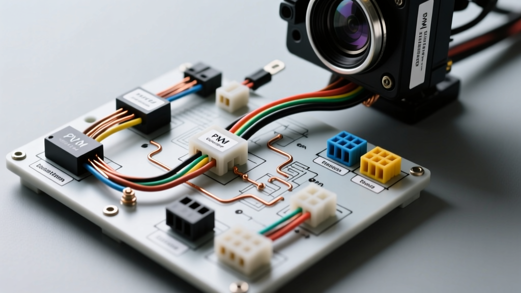
The Paradigm Shift in Modern Camera Wiring Installation
The transition from simple resistive lighting circuits to Pulse Width Modulated (PWM) and CAN-bus controlled networks has fundamentally changed how technicians approach camera wiring installation. On modern commercial and passenger platforms—such as the Ford Transit, Ram ProMaster, and newer GM full-size trucks—the Body Control Module (BCM) actively monitors exterior lighting. Tapping into the reverse light circuit the 'old-fashioned way' will almost certainly result in system failure, flickering video feeds, or BCM fault codes. This advanced technical guide details the proper methodologies for integrating high-definition backup and 360-degree camera systems into PWM-multiplexed vehicles without compromising the OEM electrical topology.
Decoding the PWM Reverse Trigger Problem
In legacy vehicles, the reverse light circuit provided a clean, steady 12V DC signal when the transmission was shifted into reverse. Modern vehicles utilize PWM to check for bulb continuity without fully illuminating the filament or triggering LED daytime running light clusters. The BCM sends a 12V square wave, typically pulsing at 400Hz to 1kHz. If you tap this circuit directly for a backup camera's 12V trigger or primary power source, the camera's internal switching voltage regulator will interpret the rapid voltage drops (from 12V to 0V) as a loss of power. This results in a flickering image, rolling horizontal bars, or the camera failing to initialize entirely.
The Capacitor Smoothing Solution
If a dedicated CAN-bus reverse trigger module is unavailable, you must isolate and smooth the PWM signal. This requires a standard 5-pin Bosch-style automotive relay and an electrolytic capacitor. By wiring the PWM reverse light wire to the relay's coil (Pin 86) and grounding the coil (Pin 85), the relay will act as a mechanical buffer. To eliminate the residual AC ripple on the relay's output, a 2200µF 25V electrolytic capacitor must be soldered in parallel across the camera's 12V power and ground lines, after the relay's switched output (Pin 87). The capacitor absorbs the voltage dips during the PWM 'off' cycles, delivering a steady 12V DC curve to the camera's voltage regulator.
CAN-Bus Integration: Bypassing the Taillights Entirely
The most reliable method for advanced camera wiring installation is to bypass the analog lighting circuits entirely and query the vehicle's CAN-bus network for the reverse gear status. This requires a CAN-bus decoder interface connected to the OBD2 diagnostic port or the BCM gateway harness.
OBD2 Pinout and CAN-Bus Topology
When utilizing the OBD2 port for a non-intrusive CAN-bus tap, adhere strictly to the SAE J1979 standard pinouts:
- Pin 6 (CAN-High): Typically White/Blue or Orange/White. Dominant voltage ~3.5V.
- Pin 14 (CAN-Low): Typically White/Brown or Orange/Brown. Dominant voltage ~1.5V.
- Pin 4 & 5 (Chassis/Signal Ground): Must be utilized for the decoder module's ground reference to prevent differential voltage errors.
By connecting a high-quality CAN-bus interface (such as those utilizing NXP TJA1050 transceivers), the module silently listens to the High-Speed CAN (HS-CAN) network. When the Transmission Control Module (TCM) broadcasts the reverse gear status PID, the interface instantly triggers a clean 12V, 300mA solid-state output to wake the camera system, completely isolating the camera from the BCM's PWM lighting diagnostics.
Wire Specifications and Routing Topologies
Signal degradation and voltage drop are the primary culprits in HD camera system failures. Standard 22 AWG zip cord is entirely insufficient for commercial vehicle runs exceeding 10 feet. Refer to the specification chart below for proper wire selection.
| Circuit Type | Recommended Wire | AWG Size | Insulation Type | Technical Notes |
|---|---|---|---|---|
| Primary 12V Power | Stranded Copper | 18 AWG | TXL (Cross-linked) | Max run 25ft. TXL required for high-temp firewall/headliner routing. |
| Chassis Ground | Stranded Copper | 16 AWG | TXL / GXL | Terminate with M6 ring terminal. Torque to 8-10 Nm on bare chassis metal. |
| HD Video (AHD/CVI) | 75-Ohm Coaxial | RG-59 / RG-6 | PE Dielectric | Must feature 95% braided copper shield. Do NOT use standard composite RCA. |
| CAN-Bus Trigger | Twisted Pair | 22 AWG | PVC / Tefzel | Maintain twist rate of 1 inch per twist to reject common-mode EMI. |
Video Signal Integrity: Shielding and Ground Loops
A critical failure point in camera wiring installation is the mismanagement of video cable shielding, leading to alternator whine or rolling ground loop bars. In HD-CVI, TVI, and AHD systems, the video signal operates at much higher frequencies than legacy NTSC composite video. Standard unshielded RCA cables act as massive antennas for Electromagnetic Interference (EMI) generated by the ignition coils and alternator stators.
Proper Shield Grounding Techniques
The braided shield of your 75-ohm coaxial cable must be grounded at one end only—preferably at the head unit or DVR chassis. Grounding the shield at both the camera head and the head unit creates a ground loop if there is a millivolt potential difference between the camera's chassis ground and the dashboard's chassis ground. This potential difference drives a low-frequency AC current through the coaxial shield, which inductively couples into the center conductor, manifesting as a 60Hz rolling bar on the display. If the camera requires a local ground for its LED array, use a 1:1 audio/video ground loop isolator (transformer-based) inline near the head unit to break the DC ground path while allowing the high-frequency RF video signal to pass.
Step-by-Step Advanced Installation Procedure
- Power Isolation: Disconnect the negative battery terminal. Wait 15 minutes for the BCM to enter sleep mode before splicing any OEM harnesses to prevent setting U-codes (Network Communication Faults).
- CAN-Bus Interface Tap: Access the BCM gateway or OBD2 port. Use TE Connectivity AMPSEAL or Molex MX150 T-tap connectors to bridge the CAN-H and CAN-L lines to the decoder module. Never use 'scotch-locks' on multiplexed data lines; they compromise the twisted-pair geometry and cause impedance mismatches.
- Camera Head Routing: Drill the rear chassis or license plate bezel using a stepped unibit. Deburr the hole and install a rubber grommet. Route the RG-59 coaxial cable along the OEM chassis harness, maintaining at least a 6-inch separation from the ignition coil primary wires and fuel injector harnesses to avoid high-voltage EMI induction.
- Relay and Capacitor Assembly: If using the PWM smoothing method, solder the 2200µF capacitor to the camera's 18 AWG power feed. Insulate with adhesive-lined dual-wall heat shrink to prevent moisture ingress and short circuits.
- Chassis Grounding: Strip the paint from the chosen chassis ground point using a fiberglass scratch pen. Apply a thin layer of dielectric grease over the bare metal after torquing the M6 ground bolt to 8-10 Nm to prevent galvanic corrosion.
Troubleshooting Decision Matrix
| Symptom | Probable Cause | Advanced Diagnostic Fix |
|---|---|---|
| Camera flickers rapidly when engine is running. | PWM ripple on the 12V power feed. | Verify capacitor polarity and capacitance. Add a 1N5408 flyback diode across the relay coil. |
| Alternator whine in audio/video feed. | Ground loop or unshielded coaxial proximity to alternator. | Install a 1:1 inline ground loop isolator. Reroute video cable away from the serpentine belt/alternator zone. |
| BCM throws 'Lighting Fault' on dash. | Camera LED draw is below the BCM's bulb-outage detection threshold. | Wire a 10-ohm, 50W power resistor in parallel with the camera's power feed to simulate an incandescent bulb load. |
| CAN-bus module fails to trigger reverse. | Module listening to wrong CAN network (e.g., MS-CAN vs HS-CAN). | Verify OBD2 Pins 3/11 (MS-CAN) vs Pins 6/14 (HS-CAN). Repin decoder harness to correct gateway network. |
Authoritative References and Standards
Proper execution of these advanced techniques requires adherence to established automotive electrical standards. For deep-dive specifications on electromagnetic compatibility and wiring topologies, consult the following resources:
- SAE J1113: Electromagnetic Compatibility Measurement Procedures and Limits - Essential for understanding EMI shielding requirements in automotive video systems.
- Motor Magazine Automotive Electrical Diagnostics - Comprehensive guides on BCM multiplexing, PWM lighting diagnostics, and parasitic draw testing.
- PAC Automotive CAN-Bus Interface Documentation - Technical whitepapers on HS-CAN and MS-CAN network decoding for aftermarket accessory integration.