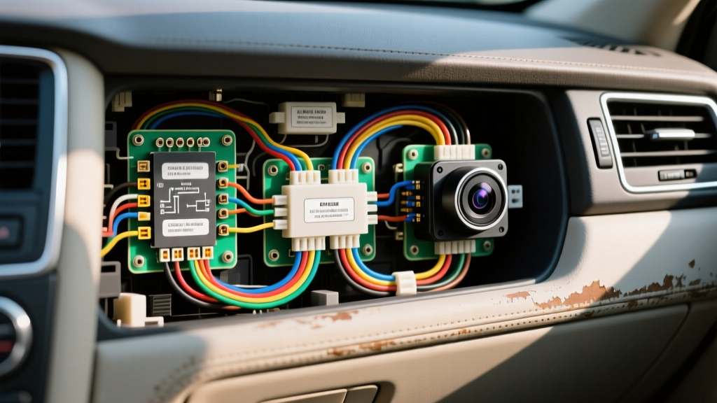
Electrical Topology for Secret Camera Installation
Executing a professional secret camera installation requires far more than simply hiding a lens behind a rearview mirror or embedding a module in the headliner. For fleet security, executive transport, and covert anti-theft surveillance, the primary electrical challenge lies in integrating the camera system into the vehicle's power network without triggering the Body Control Module (BCM) sleep faults, violating parasitic draw limits, or creating electromagnetic interference (EMI). Modern vehicles utilize complex CAN bus networks that monitor for abnormal voltage drops; a poorly executed covert tap will result in DTC (Diagnostic Trouble Code) generation, battery drain, or disabled keyless entry systems.
This technical specification reference outlines the precise wiring protocols, AWG requirements, and circuit topologies necessary for a truly hidden, electrically sound camera deployment.
Circuit Selection and AWG Requirements
Covert cameras typically draw between 250mA and 800mA during active recording, and up to 1.5A during peak boot sequences. When selecting a power source, you must avoid circuits controlled by solid-state relays or multiplexed BCM outputs, which will shut down if they detect an unauthorized load. Instead, target hardwired relay outputs or direct ignition-switched feeds.
For all low-current camera feeds, 18 AWG GXL (General Cross-Linked) stranded copper wire is the automotive standard. GXL insulation withstands under-dash temperatures up to 150°C and resists abrasion when routed behind A-pillar airbags and tight headliner channels.
| Circuit Type | Typical OEM Wire Color (Ford/GM) | Function | Max Load | Covert Tap Method |
|---|---|---|---|---|
| Constant 12V (B+) | Yellow / Red-White | Memory & Parking Mode | 10A (Fused) | BCM Constant Fuse (Micro2) |
| Ignition (IGN) | White-Red / Brown | Wake Signal / Record | 5A (Fused) | Run/Start Relay Output |
| Accessory (ACC) | Light Green / Purple | Secondary Wake | 5A (Fused) | Radio/Cigar Lighter Fuse |
| Chassis Ground | Black / Bare Copper | Return Path | N/A | M6 Bolt to Bare Metal |
Critical E-E-A-T Note: Never use a standard T-tap (scotch lock) for a covert installation. They pierce the insulation, allowing moisture ingress and copper oxidation, which increases resistance and causes voltage drop. Always use a Posi-Tap connector or, preferably, extract the OEM terminal from the fuse box connector and crimp a new pigtail using an open-barrel terminal crimper.
Covert Power Management: Hardwire Kits and LVC
A hidden camera left in 'Parking Mode' can drain a standard 12V lead-acid or AGM battery within 48 hours if not properly managed. Professional secret camera installations mandate the use of a smart hardwire kit featuring a Low Voltage Cutoff (LVC) module. The LVC monitors the B+ circuit and severs the ground path to the camera when the battery voltage drops below a specific threshold, ensuring enough cranking amps remain to start the vehicle.
Voltage Thresholds and Sleep States
According to automotive battery specifications, a standard flooded lead-acid battery rests at 12.6V. Setting the LVC too high will prematurely disable the covert camera; setting it too low risks sulfating the battery plates. The recommended LVC thresholds based on ambient temperature are:
- 11.8V (Standard): Ideal for temperate climates (above 50°F / 10°C). Leaves approximately 70% State of Charge (SoC).
- 12.0V (Winter): Required for freezing climates. Cold Cranking Amps (CCA) drop significantly in cold weather, necessitating a higher voltage reserve.
- 12.2V (AGM / Start-Stop): Mandatory for vehicles with Auto Start-Stop (ASS) systems and AGM batteries, which require higher resting voltages to initialize the BMS (Battery Management System).
CAN Bus and OBD-II Port Integration
In highly covert scenarios where running wires through the firewall or tapping the main BCM harness is impossible or too invasive, technicians often utilize the OBD-II diagnostic port. The OBD-II port is typically located under the driver's dash, hidden from plain sight, and provides direct access to the vehicle's main power bus and CAN networks.
However, tapping the OBD-II port for a secret camera installation requires strict adherence to pinout specifications to avoid shorting the CAN bus, which will immobilize the vehicle.
OBD-II Pinout Reference for Hidden Taps
| Pin | Designation | Wire Gauge | Usage in Covert Camera Install |
|---|---|---|---|
| 4 | Chassis Ground (CGND) | 16 AWG | Primary ground return for camera module. |
| 5 | Signal Ground (SGND) | 18 AWG | Reference ground for CAN decoders (do not use for main power). |
| 6 | CAN High (J-2284) | 20 AWG (Shielded) | Wake signal via opto-isolator (read-only). |
| 14 | CAN Low (J-2284) | 20 AWG (Shielded) | Wake signal via opto-isolator (read-only). |
| 16 | Battery Positive (B+) | 14 AWG | Constant 12V power (Requires inline 5A fuse). |
Warning: Pin 16 is typically unfused at the OBD port itself (protected by a main 20A or 30A fuse at the BCM). You must install an inline 3A or 5A ATO fuse within 3 inches of the Pin 16 tap. If the 18 AWG camera wire shorts against the chassis, the OEM 30A fuse will not blow before the 18 AWG wire melts, creating a severe fire hazard inside the cabin.
Grounding and EMI Shielding Specifications
Covert cameras are highly susceptible to Radio Frequency Interference (RFI) and Electromagnetic Interference (EMI), particularly when mounted near A-pillar SRS airbag modules, GPS antennas, or cellular telematics units. The SAE J1113 standard outlines the electromagnetic compatibility requirements for automotive components. To ensure your secret camera installation does not degrade the vehicle's keyless entry range or cause static on the AM/FM antenna, proper shielding and grounding are non-negotiable.
Chassis Grounding Protocol
- Locate a Factory Ground Point: Identify an existing M6 or M8 grounding bolt on the vehicle's unibody or chassis rail under the dash.
- Remove E-Coat/Paint: Use a fiberglass scratch pen or 220-grit sandpaper to remove the anti-corrosion e-coat down to bare, shiny metal. The resistance between the grounding ring terminal and the chassis must measure less than 0.5 ohms.
- Terminal Crimping: Use a closed-loop ring terminal (not a spade or quick-disconnect). Crimp using a ratcheting die matched to the 18 AWG wire.
- Torque Specification: Reinstall the OEM bolt and torque to 8-10 Nm (6-7 lb-ft). Over-torquing can strip the unibody threads; under-torquing will cause micro-vibrations that lead to intermittent camera reboots.
- Corrosion Protection: Apply a dab of dielectric grease or zinc-rich cold galvanizing compound over the terminal to prevent galvanic corrosion.
Troubleshooting Covert Camera Power Faults
When a hidden camera fails to boot, shuts down randomly, or triggers a BCM battery-saver fault, use the following decision tree to isolate the electrical failure.
| Symptom | Probable Electrical Cause | Diagnostic & Fix Procedure |
|---|---|---|
| Camera reboots during engine cranking. | Voltage drop below 9V on B+ circuit during starter engagement. | Install a supercapacitor buffer or move the B+ tap to a circuit isolated from the starter relay. Verify voltage drop with a multimeter during cranking. |
| BCM throws 'Parasitic Draw' DTC; battery dies overnight. | Camera module preventing CAN bus from entering 'Sleep' state. | Measure amperage with a multimeter in series. If draw remains >50mA after 20 mins, install a CAN-bus isolation relay to physically sever the camera's data/power link when IGN is off. |
| Video feed shows rolling horizontal lines (alternator whine). | Ground loop or poor chassis ground introducing AC ripple. | Perform a voltage drop test on the ground wire. If >0.1V under load, clean the chassis ground point and add a 1000µF inline filter capacitor on the 12V B+ feed. |
| Camera turns on, but no SD card write / corrupted files. | Insufficient amperage on ACC circuit causing brownouts during write cycles. | Move power source to a higher-amperage circuit (e.g., power seat or heated seat fuse) and ensure inline fuse is adequate. |
Airbag Routing and Safety Compliance
A critical aspect of any secret camera installation is routing the video and power cables through the A-pillar and headliner without interfering with the Supplemental Restraint System (SRS). According to the Ford Motor Company Body Builder Layout Book and general OEM upfitter guidelines, all aftermarket wiring routed down the A-pillar must be placed behind the curtain airbag deployment path, secured against the outer unibody rail using Tesa tape (fleece harness tape) and OEM-style plastic push-clips. Never zip-tie camera wires to the airbag inflator canister or the SRS yellow-sleeved wiring harness. In the event of deployment, an improperly routed wire can turn into a high-velocity projectile or alter the airbag's deployment trajectory, causing severe occupant injury and massive liability.
Conclusion
A successful secret camera installation marries stealth with rigorous automotive electrical engineering. By adhering to strict AWG sizing, utilizing GXL cross-linked wiring, implementing precise LVC thresholds, and respecting CAN bus sleep states, technicians can deploy covert surveillance systems that are entirely invisible to both the human eye and the vehicle's onboard diagnostic networks. Always verify your work with a voltage drop test and a parasitic draw measurement before reassembling the interior trim panels.