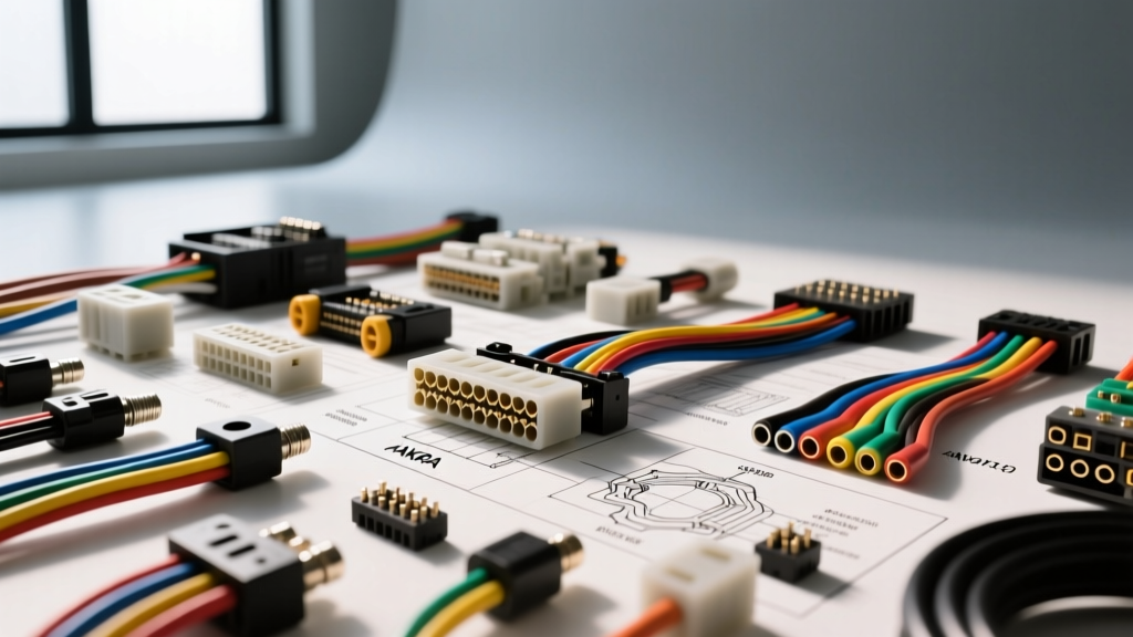
Evaluating Vehicle Security Camera Installation Cost Through Technical Specifications
When fleet managers, RV owners, and automotive technicians research the cost security camera installation, they often focus strictly on hourly labor rates and the retail price of the camera head. However, from an automotive electrical engineering perspective, the true cost and long-term reliability of a 12V or 24V surveillance system are dictated by the bill of materials (BOM) required to maintain signal integrity and prevent voltage drop across long chassis runs. A budget installation utilizing 22 AWG CCA (Copper Clad Aluminum) wire and linear voltage regulators will inevitably fail when the camera's infrared (IR) night vision engages, leading to costly diagnostic callbacks. This technical reference breaks down the hidden electrical costs, wire gauge requirements, and connector pinouts necessary for a reliable automotive security camera deployment.
Cost vs. Technical Specification Matrix
The financial outlay for a security camera system scales directly with the complexity of the signal transmission, the required shielding, and the environmental rating of the wiring harness. Below is a specification matrix comparing common automotive camera architectures to help you accurately estimate material costs.
| Architecture | Est. Material Cost (Per Run) | Wire Specification | Max Run Length | Primary Connector Type |
|---|---|---|---|---|
| Analog CVBS (Legacy) | $15 - $25 | 18 AWG Power + RG174 Coax | 35 Feet | RCA / FAKRA Z |
| AHD 1080p (Modern RV) | $35 - $60 | 16 AWG Power + Shielded Twisted Pair | 65 Feet | 4-Pin Aviation / FAKRA |
| IP / PoE (Heavy Fleet) | $85 - $140 | CAT6 S/FTP or M12 X-Coded | 300 Feet | M12 X-Coded 8-Pin |
Wire Gauge (AWG) and Routing Specifications
The most common point of failure in automotive camera installations is improper wire gauge selection, which leads to severe voltage drop. According to SAE J1128 standards for Low Tension Primary Cable, automotive wiring must withstand high temperatures and chemical exposure. You must use SAE J1128 TYPE GXL (cross-linked polyethylene insulation) wire, which features a thin wall but high heat resistance, rather than standard PVC wire that will melt against exhaust components or degrade under hood temperatures.
Calculating Voltage Drop for Camera Runs
Security cameras typically draw 150mA in day mode, but when the IR illuminator array engages at night, current draw spikes to 450mA or higher. Using the standard voltage drop formula VD = (2 x L x I x R) / 1000 (where L is one-way length in feet, I is current in amps, and R is wire resistance per 1000 ft), we can evaluate the true cost of cutting corners on wire gauge:
- 18 AWG GXL (Resistance: 6.385 Ω/kft): Over a 40-foot run to the rear of a transit van at 0.45A, the voltage drop is 2.30V. If the battery is at 12.2V, the camera receives only 9.9V, causing the IR relay to chatter and the image to reset.
- 16 AWG GXL (Resistance: 4.016 Ω/kft): Over the same 40-foot run at 0.45A, the voltage drop is reduced to 1.44V. The camera receives a stable 10.76V, well within the operational tolerance of most automotive DC-DC buck converters.
Specification Rule: Never use wire smaller than 18 AWG for the power feed, and mandate 16 AWG for any run exceeding 25 feet. For the video signal on analog systems, always use shielded coaxial cable with the shield grounded only at the head unit to prevent ground loops that manifest as horizontal rolling bars on the display.
Connector Pinouts: FAKRA Z and M12 X-Coded
Modern vehicle security cameras have moved away from consumer-grade RCA connectors toward automotive-grade, waterproof, and vibration-resistant interfaces. Understanding these pinouts is critical when fabricating custom harnesses or integrating aftermarket cameras into OEM FAKRA wiring.
FAKRA Z (Water Blue) Coaxial Pinout
The FAKRA Z connector is the industry standard for analog and AHD camera signals in automotive applications. It is a 50-ohm coaxial interface.
- Center Pin: Video Signal (Analog CVBS or AHD baseband)
- Outer Shield: Signal Ground / Shield Drain
- Plastic Housing Key: 'Z' Keyway (Water Blue) prevents mis-mating with GPS (Fakra C / Fakra Z) or cellular antennas.
M12 X-Coded 8-Pin (IP/PoE Fleet Cameras)
For heavy-duty fleet vehicles utilizing IP cameras with Power over Ethernet (PoE), the M12 X-coded connector is required. The X-coding separates the four twisted pairs, allowing for 10Gbit Ethernet speeds while simultaneously delivering up to 25.5W of PoE power. Below is the standard TIA-568B equivalent pinout adapted for M12 X-Code:
| Pin | Function | Wire Color (Standard CAT6) | PoE Power Injection |
|---|---|---|---|
| 1 | TX+ / RX+ (Pair 1) | White/Orange | Positive (+) |
| 2 | TX- / RX- (Pair 1) | Orange | Positive (+) |
| 3 | TX+ / RX+ (Pair 2) | White/Green | Negative (-) |
| 4 | TX- / RX- (Pair 2) | Blue | Negative (-) |
| 5 | TX+ / RX+ (Pair 3) | White/Blue | Positive (+) |
| 6 | TX- / RX- (Pair 3) | Green | Positive (+) |
| 7 | TX+ / RX+ (Pair 4) | White/Brown | Negative (-) |
| 8 | TX- / RX- (Pair 4) | Brown | Negative (-) |
Power Integration: BCM Tapping and PWM Filtering
A major hidden cost in security camera installation is the time required to properly integrate the power trigger without causing parasitic battery drain or CAN-bus faults. On modern vehicles (2015+ GM, Ram, Ford), the reverse light circuit and rear accessory circuits are not simple 12V DC feeds. They are driven by the Body Control Module (BCM) using Pulse Width Modulation (PWM) to monitor bulb outages. PWM signals typically operate between 500Hz and 2kHz, rapidly switching the 12V supply on and off.
The PWM Filtering Solution
If you connect a camera's trigger wire directly to a PWM-controlled reverse light, the camera will rapidly turn on and off, or fail to initialize. To rectify this, you must install a PWM filter. The most reliable, cost-effective method is soldering a 1000µF 25V electrolytic capacitor in parallel with the trigger wire, paired with a 1N4001 blocking diode in series. The diode prevents the capacitor from back-feeding the BCM, while the capacitor smooths the PWM square wave into a steady 12V DC trigger signal. This $2 component saves hours of diagnostic labor and prevents BCM fault codes.
Real-World Failure Modes: The Night Vision Reboot Loop
When auditing a failed security camera installation, technicians frequently encounter the 'Night Vision Reboot Loop.' This occurs exclusively when the ambient light sensor triggers the IR LED array. The sudden 300mA current spike causes the voltage at the camera head to drop below the threshold of the internal linear voltage regulator (typically an LM7805 or similar). The regulator experiences thermal shutdown or voltage starvation, rebooting the camera. As the camera reboots, the IR LEDs turn off, voltage recovers, the camera boots, the sensor detects darkness, the IR LEDs turn on, and the cycle repeats infinitely.
The Technical Fix: Never rely on the camera's internal linear regulator for long chassis runs. Install an external, automotive-grade DC-DC switching buck converter (such as the RECOM R-78E12-0.5) near the power source. Step the 14.4V alternator charge down to a regulated 12.0V before sending it down the 16 AWG GXL harness. This ensures that even with a 1.5V drop across the wire, the camera still receives a minimum of 10.5V, entirely eliminating the reboot loop and extending the lifespan of the camera's internal logic board.
Authoritative References
- SAE International: J1128 Low Tension Primary Cable Standards - Specifications for GXL and TXL automotive wire insulation and temperature ratings.
- Rosenberger Automotive FAKRA Standards - Impedance and keyway coding specifications for Z-type coaxial camera connections.
- Mobile Electronics Association (MEA) - Best practices for 12V integration, PWM filtering, and parasitic draw limits in aftermarket fleet installations.